Facebook
 Google
 GitHub
 Linkedin
There is this "shaking torch" project that I am revisiting. It is where you shake this thing and a powerful magnet generates a few volts AC in a coil (I have found a max of ~ 2.5V AC RMS). Then it charges a supercap or battery, which powers a light or something. This way, it is not dependent upon batteries. It would be good if you were stranded in the woods or somewhere else, or can never seem to find batteries. I kind of gave up before because I did not have all the required parts, and there were BIG power losses.
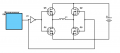
Now, I want to design a more efficient and practical design. I should be getting some buck and boost converters, N- and P-channel MOSFETs, and other parts soon. The first part of the shaking torch circuit must rectify the AC. This is where I lost a lot of power before, with a silicon FBR. Up to 1.2V (with 2 diodes), so 1/2 of the power! But I have heard about using MOSFETs for rectification (though mainly for reverse polarity protection), with minimal power losses. So how would I go about building a FBR with MOSFETs? Is this possible and practical?
Also, here is my plan for the whole project:
~2.5 VRMS AC from coil & magnet --> MOSFET full bridge rectifier (to get~2.5V DC) --> supercap (5.5V rated, 7.5F, 90 mOhms) --> on/off switch --> resistor (.5 to 10 Ohms) or something else here? --> boost converter (to constant 3.3 V) --> LEDs (80 - 120 mA at 3.3V)
So is it wise to place a resistor in series with the boost converter? If so, what value? I am leaning towards using a low value one, but is that ideal for the boost converter working for low cap voltages and charging the cap faster? I need it to work from 2.5V down to .35-.5V. I am also concerned about the converter exponentially needing more current, and getting fried by the cap. So what is a good solution to these problems, with minimal other parts? Thanks.