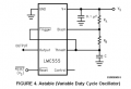
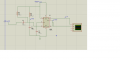
monostavble circuit ne555 problem of blocage

Thread Starter

youcef hassan

Joined Dec 9, 2016
38
Hello I am trying to make this circuit but I have a problem that in the second timmer the pin 6 and 7 makes 0 v when they attached to capacitor but when i detach the wire from the pinsthe voltage makes 11v , I am tryied to simulate the problem by the ISIS Proteus the results was , it s works well just for 1 second then the second timmer stop , please is there a solution for this problem? thanks
 

AlbertHall

Joined Jun 4, 2014
12,636
On U1, you have the connections to pins 6 and 7 reversed.
Pin 6 should be connected to the junction of the two 4.7k resistors.
Pin 7 should be connected to the capacitor.
 

Thread Starter

youcef hassan

Joined Dec 9, 2016
38
Which wire? Voltage where?
Pin 2 of U2 gets driven to about twice the supply voltage when pin 3 of U1 goes high. Perhaps that upsets U2.
Hello sir , thanks for the answer ,the problem is in U2 pin 6 and 7 , when I attach them to the capacitor 0.1u the voltage became 0 volts , and when I deconnect the wire from the 6 pin and 7 pin of the U2 , the voltage on the point betwen the capacitor 0.1uF and resistor 2.2k makes about 11v, sorry for my bad english
 

AnalogKid

Joined Aug 1, 2013
12,184
Pin 7 holds the voltage across the timing capacitor to almost 0 V until the circuit is triggered. If the astable circuit is not running correctly, the monostable will fire once and then stop. Are you sure the astable oscillator is running correctly?

As a test, try this. Remove the 0.001 uF capacitor. Attach a short wire to U2 pin2 and the 10K resistor. Each time you touch the wire to GND, the monostable should produce an output pulse. If this works, the problem is in the U1 circuit. If this does not work, the problem is in the U2 circuit.

ak
 

Alec_t

Joined Sep 17, 2013
15,132
the problem is in U2 pin 6 and 7 , when I attach them to the capacitor 0.1u the voltage became 0 volts , and when I deconnect the wire from the 6 pin and 7 pin of the U2 , the voltage on the point betwen the capacitor 0.1uF and resistor 2.2k makes about 11v,
That is what you would expect. Pin7 keeps the cap discharged until the monostable is triggered. If you disconnect the cap from those pins then the 2.2k resistor and pot pull the cap voltage high.
 

bertus

Joined Apr 5, 2008
22,956
Hello,

Linking images to your local diskdrive will not work.
Please upload the image using the "upload a file" button.

Bertus
 

Thread Starter

youcef hassan

Joined Dec 9, 2016
38
fence11.png fence12.png fence11.png fence12.pngthe probleme is here: when I connect pin 6 and 7 to the capacitor the voltage R1(Z) gives me 0 v , but in the first pic when I diconnect the wire from the capacitor R1(Z) gives me about 11 v , why ?
 

AnalogKid

Joined Aug 1, 2013
12,184
Because pin 7 is pulling it to GND. Without waveforms it is very difficult to explain. The text in the images is very small and hard to read. What is the input waveform going into C3? What is the waveform at the output pin 3? what is the waveform across capacitor C1?

ak
 

Thread Starter

youcef hassan

Joined Dec 9, 2016
38
Hello , The problem is resolved , the problem was in the value of the capacitor , I change the 0.1uF by an 10uF and all things is good; thanks for all your helps
 

Audioguru

Joined Dec 20, 2007
11,248
On U1, you have the connections to pins 6 and 7 reversed.
Pin 6 should be connected to the junction of the two 4.7k resistors.
Pin 7 should be connected to the capacitor.
No, the circuit is correct, you are wrong.

Also, the datasheet of the NE555 shows pin 2 being fed a negative pulse though a coupling capacitor exactly as shown in this circuit.
 

Attachments

Top