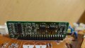
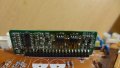
Monitor not powering on, ticking noise comming from power board.

Status
Not open for further replies.

Thread Starter

TwentyØnePenguins

Joined Apr 29, 2018
24
Okay, I tried swapping the 10 uF 50V cap for a 22 uF 50v one like I mentioned before.
It didn't blow up, yay, but it still has the clicking. However, it sounded like the clicks where slower, if that makes sense.
 

ebp

Joined Feb 8, 2018
2,332
If you look at the datasheet for the LD7575 you will see almost exactly what I described. The difference is that the startup current to charge the capacitor is via the HV pin of the IC, rather than directly to the capacitor. Page 8 of the datasheet describes the operation.

The circuit in the datasheet is very typical of a current-mode flyback converter. Your monitor board will be very similar except that it will have multiple outputs to supply different voltages for different parts of the circuit (looks like probably just 2, plus the one that powers the control circuit). The cycle-by-cycle current limiting for the FET, while not rendering the circuit indestructible, goes a long way to preventing damage from several possible problems.

There should be no risk in using the 22 µF capacitor. A cap in that position is not directly in the feedback path but is critical to circuit operation.

---
Just about to post when you update arrived -
Yup, lower click rate makes sense. The problem now is to try to identify what is causing the overload. It may be in the inverter for the cold-cathode fluorescent tubes - the larger daughter board, however it could be in one of the main rectifiers on the output side. These are the devices mounted on the heatsinks near the transformer.
 

Thread Starter

TwentyØnePenguins

Joined Apr 29, 2018
24
If you look at the datasheet for the LD7575 you will see almost exactly what I described. The difference is that the startup current to charge the capacitor is via the HV pin of the IC, rather than directly to the capacitor. Page 8 of the datasheet describes the operation.

The circuit in the datasheet is very typical of a current-mode flyback converter. Your monitor board will be very similar except that it will have multiple outputs to supply different voltages for different parts of the circuit (looks like probably just 2, plus the one that powers the control circuit). The cycle-by-cycle current limiting for the FET, while not rendering the circuit indestructible, goes a long way to preventing damage from several possible problems.

There should be no risk in using the 22 µF capacitor. A cap in that position is not directly in the feedback path but is critical to circuit operation.

---
Just about to post when you update arrived -
Yup, lower click rate makes sense. The problem now is to try to identify what is causing the overload. It may be in the inverter for the cold-cathode fluorescent tubes - the larger daughter board, however it could be in one of the main rectifiers on the output side. These are the devices mounted on the heatsinks near the transformer.
I never said this stuff was easy, but damn, this is complicated xD
I'll remove the caps blocking the larger daughter board so I can get a better look...

(I do really feel like buying a better soldering iron)
 
Last edited:

Thread Starter

TwentyØnePenguins

Joined Apr 29, 2018
24
I think I'm calling it for tonight, it's getting quite late here, so if I'm not replying that's why :p
And I guess I should look into getting a multimeter :)
 

Thread Starter

TwentyØnePenguins

Joined Apr 29, 2018
24
The problem now is to try to identify what is causing the overload. It may be in the inverter for the cold-cathode fluorescent tubes - the larger daughter board, however it could be in one of the main rectifiers on the output side. These are the devices mounted on the heatsinks near the transformer.
Oh and by the way, whats the best way to test these? :)
 

DickCappels

Joined Aug 21, 2008
10,662
Haven't seen it mentioned, so I will mention it: Sometimes a shorted output rectifier causes this. Effectively driving an output capacitor through a shorted diode will put a heck of a load on the power supply.
 

Thread Starter

TwentyØnePenguins

Joined Apr 29, 2018
24
Haven't seen it mentioned, so I will mention it: Sometimes a shorted output rectifier causes this. Effectively driving an output capacitor through a shorted diode will put a heck of a load on the power supply.
I really feel like this isn't a good beginner project xD
Anyhow, picking up a multimeter now so I can test the stuff. (when i figure out how to do so :D )
 

ebp

Joined Feb 8, 2018
2,332
First try checking the output rectifiers (on heatsinks) for shorts. You should be able to do this with them in-circuit.

I can't tell from the photo what the pin configurations are. Often dual diodes connected in parallel are used. The centre pin is usually the cathode and the outside pins the anodes. Sometimes the devices are single diodes. You'll be able to tell from looking at the solder side, and may even find a useful something in the "silkscreen" printing.

Diodes typically fail short circuit. If you measure across the diode with the normal resistance range on you meter it should indicate an open circuit or at least a high (tens of kilohms or more) resistance. The reading may take some time to stabilize with the resistance reading rising because the capacitor will charge through the transformer winding - but if you see that happening it generally means the diode is OK.

If your meter has a diode checking function, you can also use that. With one polarity it should show essentially open circuit and with the other polarity it should show the "forward voltage" of the diode, which should be in the range of about 0.3 to 0.7 volts, depending on the diode type.

Before you attempt to make these measurements it is best to be sure the capacitors are discharged. Just measure with the DC voltage range of you meter. You can discharge the caps by shorting them, but you make get a bit of a spark - not dangerous, but startling if you don't expect it.

Measuring the voltage across the capacitors can also be a way of detecting either diode problems or load problems. If you try to power up the board then quickly measure the voltage across the capacitors after disconnecting the AC input, you may find a small voltage on caps in the "good" part of the circuit and zero or very low voltage on caps in the "bad" part. Be really careful to avoid contact with the long capacitor near the AC input, since it might hold a substantial charge for some time. Sometimes it is worth soldering some wires to things you want to measure in-circuit so you can use clip leads to connect to a meter and actually monitor with power applied.
 

Thread Starter

TwentyØnePenguins

Joined Apr 29, 2018
24
First try checking the output rectifiers (on heatsinks) for shorts. You should be able to do this with them in-circuit.

I can't tell from the photo what the pin configurations are. Often dual diodes connected in parallel are used. The centre pin is usually the cathode and the outside pins the anodes. Sometimes the devices are single diodes. You'll be able to tell from looking at the solder side, and may even find a useful something in the "silkscreen" printing.

Diodes typically fail short circuit. If you measure across the diode with the normal resistance range on you meter it should indicate an open circuit or at least a high (tens of kilohms or more) resistance. The reading may take some time to stabilize with the resistance reading rising because the capacitor will charge through the transformer winding - but if you see that happening it generally means the diode is OK.

If your meter has a diode checking function, you can also use that. With one polarity it should show essentially open circuit and with the other polarity it should show the "forward voltage" of the diode, which should be in the range of about 0.3 to 0.7 volts, depending on the diode type.

Before you attempt to make these measurements it is best to be sure the capacitors are discharged. Just measure with the DC voltage range of you meter. You can discharge the caps by shorting them, but you make get a bit of a spark - not dangerous, but startling if you don't expect it.

Measuring the voltage across the capacitors can also be a way of detecting either diode problems or load problems. If you try to power up the board then quickly measure the voltage across the capacitors after disconnecting the AC input, you may find a small voltage on caps in the "good" part of the circuit and zero or very low voltage on caps in the "bad" part. Be really careful to avoid contact with the long capacitor near the AC input, since it might hold a substantial charge for some time. Sometimes it is worth soldering some wires to things you want to measure in-circuit so you can use clip leads to connect to a meter and actually monitor with power applied.
Thanks for the info!
I've tested the three on heatsinks (All of them have 3 legs, can post pictures if required.) From one I get nothing, from the second I get around .243v on both legs, but the third stands out too me. On one leg I get around .464v, but on the other, I get 1.704v. I don't know if this is supposed to be the case, but it seems a little odd to me that one would be so much higher then the other...
(This was quite vague, if you need more details let me know.)
 

Dodgydave

Joined Jun 22, 2012
11,395
How many outputs are on the psu? Can you test across each of the outputs ( with the psu turned off) and check for shorts with diode test or low resistance.
Also the Shotkley diodes are usually 220 to 450mV on diode, the centre pin is Cathode you need to disconnect them from the transformer before testing .
 

Thread Starter

TwentyØnePenguins

Joined Apr 29, 2018
24
How many outputs are on the psu? Can you test across each of the outputs ( with the psu turned off) and check for shorts with diode test or low resistance.
Also the Shotkley diodes are usually 220 to 450mV on diode, the centre pin is Cathode you need to disconnect them from the transformer before testing .
By outputs, you mean the 10 wires running to the LCD control board? I'm really not very experienced :D
When desoldering one of the diode with the high readings, i got .000
Is that supposed to happened, or am i doing something wrong?
 

ian field

Joined Oct 27, 2012
6,536
The replacement capacitors were all Panasonic ones, and I made sure to orient them correctly. All have the same uF rating, however, some are rated 35v instead of 25v like the original ones, but according to what I've read, that should be fine. However, when I ordered those, I completely missed that small one (rated 10 uF 50v). So maybe replacing that would be a good idea, or what do you think?
There's a discussion elsewhere about thickness of oxide dielectric layer on aluminium capacitors, running undervoltage thins the layer and increases capacitance - eventually. ripple on whichever rail is sensed for voltage regulation can cause unpredictable malfunction - look for power stages like audio amplifiers that might have fried.
 

Thread Starter

TwentyØnePenguins

Joined Apr 29, 2018
24
There's a discussion elsewhere about thickness of oxide dielectric layer on aluminium capacitors, running undervoltage thins the layer and increases capacitance - eventually. ripple on whichever rail is sensed for voltage regulation can cause unpredictable malfunction - look for power stages like audio amplifiers that might have fried.
I'm having a little trouble deciphering what you just said :D
 

Dodgydave

Joined Jun 22, 2012
11,395
By outputs, you mean the 10 wires running to the LCD control board? I'm really not very experienced :D
When desoldering one of the diode with the high readings, i got .000
Is that supposed to happened, or am i doing something wrong?
Yes you're doing it all wrong, i get the feeling you won't get this fixed as you don't have the knowledge to repair it..
 

Thread Starter

TwentyØnePenguins

Joined Apr 29, 2018
24
Yes you're doing it all wrong, i get the feeling you won't get this fixed as you don't have the knowledge to repair it..
Oh okay, I mean, I'm trying to get an understanding of how this works, so I can fix it. And I'm writing here in the first place in order to get help from people who know this stuff. And if you don't want to bother with it, you don't have to, that's totally fine
 
Status
Not open for further replies.
Top