True.
But in this application, I would think as long as the pulse-width is above a minimum value, it will work properly.
Since a long pulse should not be a problem, it probably would be good to start with a larger RC value, such as 100uF for C1
The gives a nominal pulse-width of about 0.8s, which should be more than sufficient.
This is where I tend to get confused, so the VDD would just be the 12V supply that I am using to power the video camera?
Can anyone answer my queries 2-4? (reposted below)
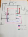
2) Does the capacitor just go to ground as I have it here
3) If I run the pulse through the reed relay and then to ground that should to the momentary switch operation right?
4) What would the voltage of the pulse be?
Likely you will need to add a transistor buffer, such as a 2N7000 (below), to drive the relay, as the CD4093 can only output a mA or so.
The actual relay current will depend upon the relay selected.
1. Per the datasheet, pin 14 is Vdd, the positive supply rail (+12 V, +5 V, whatever); pin 7 is Vss, the negative supply rail - Ground.
2. Yes.
3. Yes, but the 4093 probably cannot source enough current to drive the relay coil directly. A small outboard transistor such as a 2N7000 can handle the 25 mA load.
4. With no load on the output pin, the peak output voltage will be very near the value of the power supply voltage.
I get that you are new at this, so take this as friendly guidance.
The reason a schematic diagram uses device symbols rather than package outlines is that package outlines do not contain enough *design* information. Looking at Wally's schematic of the circuit, anyone who knows what a NAND symbol represents can figure out the circuit's operation without have a clue about the physical package or pin arrangements. The only thing missing are the pin numbers. Same for the extra transistor - connections to a MOSFET symbol can be evaluated instantly, without looking up the datasheet to see which pin does what.
Design and production documents are different; they have different information for different uses. Start with a schematic with schematic symbols that capture the intent and the specifics of the design. Once that is ironed out, move on to a production drawing with the physical package geography. This might seem like unnecessary extra effort for a one-off quickie circuit; it isn't.
ak
ps. The 2N7000 is connected incorrectly **IF** the symbol you drew represents the front (flat) side view of the part.
It's not correct.
You need to have the source pin to ground and the drain pin connected to one of the relay's coil terminals.
The other relay coil pin goes to +12V.
Take another look at my schematic in post #24 (or below).
Yes, that is an issue, since the CD4093's input threshold voltage is about 6V with a 12V supply.
You need to increase the pulse voltage to 12V, which can be done with another 2N7000 (below).
One other consideration, the discharge of the 100 uF timing cap if
Vdd is grounded. CMOS inputs have parasitic diodes to supply rails.
If Vdd is grounded while 100 uF is charged, could cause damage to
diode and surrounding regions on die due to excess current flow out
of cap.
Maybe a series R with input can ameliorate this issue.
Note most supplies, when turned off, do not short their rail to ground.
But if rail rapidly discharged due to large loads it can effect a "short to
ground" causing this issue to be of concern.
Also there are some CMOS inputs that have well isolation where this
is not a problem. But standard logic families do have the parasitic diodes.
Bottom line, do not tie large value caps directly to CMOS logic inputs
and outputs.
This is where I tend to get confused, so the VDD would just be the 12V supply that I am using to power the video camera?
Can anyone answer my queries 2-4? (reposted below)
2) Does the capacitor just go to ground as I have it here
3) If I run the pulse through the reed relay and then to ground that should to the momentary switch operation right?
4) What would the voltage of the pulse be?
Does the circuit need to send one pulse at a time to trigger the camera?
That is....one pulse to start recording, followed by one pulse some time later to stop recording?
If so, then a circuit to toggle the record function is needed.
That requires a different circuit than the XOR edge-detector circuit that was mentioned.
That is a possible problem.
Connecting a 10kΩ resistor between the capacitor and CD4093 inputs will protect it from any excessive current without affecting the circuit performance in this application.
That's my understanding.
One pulse to start recording when the input goes high, and another pulse to stop recording when the input goes low.
That's what the XOR circuit does.
That's my understanding.
One pulse to start recording when the input goes high, and another pulse to stop recording when the input goes low.
That's what the XOR circuit does.
I'm trying to repurpose a number of old video cameras that use the old 10 pin connection. One of the pins on the connector is the remote control or trigger pin to start and stop recording. This was used when the operator pressed the record button to make a constant current flow which would start the VTR recording - when pressed again the circuit was cut and the VTR would stop recording.
I am using a drone FPV recorder to connect with these old cameras as these are tiny devices that capture composite video to micro SD card .........
They come with breakout cable to operate each of the buttons, one of which is of course the record button. This is a momentary start/stop switch and what I want to do is hook it up to the trigger cable on the camera to start and stop recording on the FPV recorder
From that I concluded that the signal to the recorder is a steady positive voltage when it is recording and 0V when stopped.
However the camera needs a pulse to start and another pulse to stop.
So the XOR circuit provides a pulse for the camera to turn it one when the record voltage goes high that starts the recorder, and another pulse to turn the camera off when the record voltage goes low that stops the recorder.
Not sure what you mean by "contiguous".
The TS stated the following:
He also stated:
From that I concluded that the signal to the recorder is a steady positive voltage when it is recording and 0V when stopped.
However the camera needs a pulse to start and another pulse to stop.
So the XOR circuit provides a pulse for the camera to turn it one when the record voltage goes high that starts the recorder, and another pulse to turn the camera off when the record voltage goes low that stops the recorder.
Yes...I meant consecutive pulses.. the way I read it...the TS wants one pulse at a time..one to start recording and then one some time later to stop recording.
Yes...I meant consecutive pulses.. the way I read it...the TS wants one pulse at a time..one to start recording and then one some time later to stop recording.
Yes that's right. one momentary pulse when the camera trigger goes to high and another identical one when the camera trigger goes to low. During the recording the camera trigger voltage will remain constantly high, and when not recording - constantly low.
Regarding @crutschow post above about the transistor. I will adjust my diagram accordingly. Regarding the voltage, like I said the trigger voltage can vary depending on the camera that is attached. Typically in the range 6-9v, how can I accommodate for this differentiation. Will the 2nd 2N7000 be enough to balance this?
There is also another post about connecting another 10k resistor to avoid issues with the capacitor, would that be between the capacitor and pin 2?
 Facebook
 Google
 GitHub
 Linkedin