Facebook
 Google
 GitHub
 Linkedin
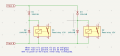
On my N gauge model railway I have used reeds and latching relays to control my signals. I want to switch a relay to automatically identify when the direction of a particular track is forward or reverse so that the correct signals are energised.
See my railway here.
See my railway here.