Mod 14 4 bit JK Flip Flop getting messed up after 1 cycle

Thread Starter

dasPhillipBrau

Joined Oct 30, 2019
24
Hello.

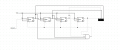
I've been trying to design a MOD14 circuit using 4 JK flip flops, but I've been getting the issue where, after the count resets to 0 (After counting to 13) the count will only go up to 3 and then it will reset from there and never get past 3.

In other words, I have 1 successful count to 13, but after that, it never goes above 3.

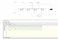
Anyone knows what might be wrong? I'm attaching my diagram and you can see the logic history as well.Mod14.PNG
 

Attachments

Papabravo

Joined Feb 24, 2006
21,225
It might be because you have an asynchronous circuit with race conditions. Make your circuit synchronous, so all FFs change on the clock edge. That way your decoders can avoid glitches where it might do some damage.

Where does the output of the 3 input AND gate go? Does it RESET the FF's to 0 ASYNCHRONOUSLY? Why don't you RESET Q1 to zero?
Are you just fooling around or did somebody teach you to design counters this way?
 
Last edited:

Thread Starter

dasPhillipBrau

Joined Oct 30, 2019
24
Welcome to AAC! Kudos to you for making an attempt before asking for help and posting a schematic.
Could you post the complete text of the problem? It's more typical for students to be asked to design synchronous counters.
It might be because you have an asynchronous circuit with race conditions. Make your circuit synchronous, so all FFs change on the clock edge. That way your decoders can avoid glitches where it might do some damage.

Where does the output of the 3 input AND gate go? Does it RESET the FF's to 0 ASYNCHRONOUSLY? Why don't you RESET Q1 to zero?
Are you just fooling around or did somebody teach you to design counters this way?
Thank you. I'm being asked specifically to make an Async counter.

"Using 4 JK flip flops, design an Async counter that goes from o to 13"

I did later connect the AND gate to the reset of first JK as well, but it didn't change anything.
 

ci139

Joined Jul 11, 2016
1,898
• you need to "program" / handle all transitions (input changes & times of change) of all counter stages (it might seem confusing at first)
.
• the JK-chain may "enter an alternate mode/cycle/loop" you may need to provide additional circuitry to initialize it to or enter the desired one of these
______
You start actually from your transition diagram :
Code:
◄ 13 ►◄ _0 ►◄ _1 ►◄ _2 ►◄ _3 ►◄ _4 ►◄ _5 ►◄ _6 ►◄ _7 ►◄ _8 ►◄ _9 ►◄ 10 ►◄ 11 ►◄ 12 ►◄ 13 ►◄ _0 ► ← Count
__/¯¯\__/¯¯\__/¯¯\__/¯¯\__/¯¯\__/¯¯\__/¯¯\__/¯¯\__/¯¯\__/¯¯\__/¯¯\__/¯¯\__/¯¯\__/¯¯\__/¯¯\__/¯¯\ ← CLK
¯¯¯¯¯\___0_/¯¯¯1¯\___2_/¯¯¯3¯\___4_/¯¯¯5¯\___6_/¯¯¯7¯\___8_/¯¯¯9¯\___A_/¯¯¯B¯\___C_/¯¯¯D¯\___0_/ ← Bit-0
_________________/¯¯¯¯¯¯¯¯¯¯¯\___________/¯¯¯¯¯¯¯¯¯¯¯\___________/¯¯¯¯¯¯¯¯¯¯¯\__________________ ← Bit-1
¯¯¯¯¯\_______________________/¯¯¯¯¯¯¯¯¯¯¯¯¯¯¯¯¯¯¯¯¯¯¯\_______________________/¯¯¯¯¯¯¯¯¯¯¯\______ ← Bit-2
¯¯¯¯¯\_______________________________________________/¯¯¯¯¯¯¯¯¯¯¯¯¯¯¯¯¯¯¯¯¯¯¯¯¯¯¯¯¯¯¯¯¯¯¯\______ ← Bit-3
- - - - - - - - - - - - - - - - - - - - - - - - - - - - - - - - - - - - - - - - - -▲_____▲ - - - ← An "Intecept point"
The following applies @ ( and BEFORE ) the CLK's Hi-to-Lo transition (the intercept point) before each count 0 / after each count 13
• The no. 14 has parity EVEN thus the Bit Zero alternates at half of the CLK's frequency from 0 to 1 -- thust it goes from it's 1 (@ ct.13) to 0 (@ ct.0 that'll follow)
• Bit One is low and stays low -- thus you either (1) must disable a clock input for it or (2) set it's JK both to Low ( by the prev. condition 0xD (hex) 1101 (binary) )
• Bit Two is high and becomes low -- thus (1) it must be driven ( by the prev. condition 0xD (hex) 1101 (binary) ) ← you need to work it out how ... (has many options)
• Bit Three is high and becomes low -- thus (1) you can use Bit Two (as it's clock input) to drive it
 
Last edited:

Papabravo

Joined Feb 24, 2006
21,225
OK I understand the counter must be asynchronous. The reason JK FFs were invented is because they can be placed in 4 different states depending on the JK inputs. The four states are:
  1. Set to 0
  2. Set to 1
  3. Toggle
  4. Hold
This allows you to change which stages toggle and which stages don't.
 

Thread Starter

dasPhillipBrau

Joined Oct 30, 2019
24
What are you trying to do with the sequence generators?
In the simulation software, the sequence generators are the ones where you feed the binary sequence into, without them the flip flops wouldn't do anything.

i.e the MSB has a sequence of 0000000011111111

• you need to "program" / handle all transitions (input changes & times of change) of all counter stages (it might seem confusing at first)
.
• the JK-chain may "enter an alternate mode/cycle/loop" you may need to provide additional circuitry to initialize it to or enter the desired one of these
______
You start actually from your transition diagram :
Code:
◄ 13 ►◄ _0 ►◄ _1 ►◄ _2 ►◄ _3 ►◄ _4 ►◄ _5 ►◄ _6 ►◄ _7 ►◄ _8 ►◄ _9 ►◄ 10 ►◄ 11 ►◄ 12 ►◄ 13 ►◄ _0 ► ← Count
__/¯¯\__/¯¯\__/¯¯\__/¯¯\__/¯¯\__/¯¯\__/¯¯\__/¯¯\__/¯¯\__/¯¯\__/¯¯\__/¯¯\__/¯¯\__/¯¯\__/¯¯\__/¯¯\ ← CLK
¯¯¯¯¯\___0_/¯¯¯1¯\___2_/¯¯¯3¯\___4_/¯¯¯5¯\___6_/¯¯¯7¯\___8_/¯¯¯9¯\___A_/¯¯¯B¯\___C_/¯¯¯D¯\___0_/ ← Bit-0
_________________/¯¯¯¯¯¯¯¯¯¯¯\___________/¯¯¯¯¯¯¯¯¯¯¯\___________/¯¯¯¯¯¯¯¯¯¯¯\__________________ ← Bit-1
¯¯¯¯¯\_______________________/¯¯¯¯¯¯¯¯¯¯¯¯¯¯¯¯¯¯¯¯¯¯¯\_______________________/¯¯¯¯¯¯¯¯¯¯¯\______ ← Bit-2
¯¯¯¯¯\_______________________________________________/¯¯¯¯¯¯¯¯¯¯¯¯¯¯¯¯¯¯¯¯¯¯¯¯¯¯¯¯¯¯¯¯¯¯¯\______ ← Bit-3
- - - - - - - - - - - - - - - - - - - - - - - - - - - - - - - - - - - - - - - - - -▲_____▲ - - - ← An "Intecept point"
The following applies @ ( and BEFORE ) the CLK's Hi-to-Lo transition (the intercept point) before each count 0 / after each count 13
• The no. 14 has parity EVEN thus the Bit Zero alternates at half of the CLK's frequency from 0 to 1 -- thust it goes from it's 1 (@ ct.13) to 0 (@ ct.0 that'll follow)
• Bit One is low and stays low -- thus you either (1) must disable a clock input for it or (2) set it's JK both to Low ( by the prev. condition 0xD (hex) 1101 (binary) )
• Bit Two is high and becomes low -- thus (1) it must be driven ( by the prev. condition 0xD (hex) 1101 (binary) ) ← you need to work it out ...
• Bit Three is high and becomes low -- thus (1) you can use Bit Two (as it's clock input) to drive it
Sorry, but I don't really understand anything about what this means...And I really don't think it's the solution because we have not seen any of this in the course either.
 

dl324

Joined Mar 30, 2015
16,909
In the simulation software, the sequence generators are the ones where you feed the binary sequence into, without them the flip flops wouldn't do anything.

i.e the MSB has a sequence of 0000000011111111
You can tie the JK inputs to Vcc which will make them toggle.

The sequence you're using makes no sense.
 

Thread Starter

dasPhillipBrau

Joined Oct 30, 2019
24
You can tie the JK inputs to Vcc which will make them toggle.

The sequence you're using makes no sense.
This is just the simulation software, mate, there's no Vcc option in it.

It's the way it works there, you use sequence generators which are basically just "voltages". Each sequence corresponds to values in truth table, so there's 4 sequences = 16 possible combinations and these represent the binary numbers.

so when your sequence (1 digit per bit) looks like 0010 you'll get a 2 in the numeric output...

You can see these values in the original post on the logic history. The pulses from Q1 to Q4 are really just 1s and 0s coming from the sequence generator (and in fact, the Q1 and Q4 are the sequence generators themselves)
 

dl324

Joined Mar 30, 2015
16,909
In my version that's called Vdd instead of Vcc. Regardless, as a requisite they ask us for the values used for the sequences
What do you think you're accomplishing with the sequencers on the inputs? You'd have an asynchronous binary counter if you connected the JK to a logic HIGH. You're decoding 14 as the reset, so the problem is the sequencers.

Could you post the full text of the problem where it requires you to use sequencers?
 

dl324

Joined Mar 30, 2015
16,909
This is what I think you've implemented (first 9 traces):
1572558888509.png
Note that the count only increments on every other clock.

The bottom 4 traces show the output from a correctly wired counter.
 

Thread Starter

dasPhillipBrau

Joined Oct 30, 2019
24
What do you think you're accomplishing with the sequencers on the inputs? You'd have an asynchronous binary counter if you connected the JK to a logic HIGH. You're decoding 14 as the reset, so the problem is the sequencers.

Could you post the full text of the problem where it requires you to use sequencers?
Hey, first of all: Thanks a lot for the tip about the Vcc, I checked DW again and it does say Vcc in my version (so I guess I saw Vdd from another diagram and thought it was missing in DW, I honestly don't like DW much)

So I replaced all of the sequence generators for a single Vcc and...the counter works now.
However, I'm still a bit worried that the faculty won't accept it, but I will call them tomorrow to confirm.

The exact translation of the instructions were just

"Design an async counter, using 4 Jk flip flops, which counts from 0 to 13" (Note: This was actually changed today and they said it was actually 0 to 14, not 0 to 13) "Keep in mind that, since it's 4 JK flip flops, the counter could count up to 15, but it should restart after 14, so in other words: 15 should not be displayed. The output must be displayed in a numeric output component, as present in digital works."

And now there's the evaluation breakdown, which lists "Must include a report explaining how the circuit works, include truth tables, procedure used and a justification for chosen solution."

It seems I got it mixed up, I thought that they asked for sequence generators because I remember reading they also required the logic history (without sequence generators, for this circuit, that would only be the clock, since vcc can't be added to LS in DW, and that isn't very helpful), but I guess I was just mixing "logic history" with "truth tables".

However, I'm curious about three things now:

Why is it bad to use sequence generators for these type of things? This wasn't really covered in the course as far as I know.

And why was it breaking with these sequences?, they were the standard sequences showing all 16 combinations for 4 different variables.

Lastly, if there's no sequences, where can I calculate the truth table from?

Once again, thank you for the solution. Here's the final, working circuit :)
working.PNG
 

Attachments

Top