
Mixing white and pink noise

MrAl

Joined Jun 17, 2014
13,726
The circuit he has will work just fine, as-is. With the pot at one end, all of the signal will come from the pink source and none from the white source; with the pot at the other end, all of the signal will come from the white source and none from the pink source. And with the pot in the middle, 50% will come from each.
Hi,

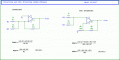
Yes perhaps, but the non inverting version takes one extra resistor. Not a big deal i guess, but i just thought that as long as he is using an op amp might as well take advantage of the adding property of the inverting terminal. The non inverting version also might be able to take higher input voltages, depending on gain setting.
See next post for summary.
 
Last edited:
MrAl

Joined Jun 17, 2014
13,726
Are you talking about configuring it as an inverting instead of non-inverting amp, feeding the signal into the inverting input?

When I read up on audio summing and mixing amps, I found numerous examples of both inverting and non-inverting styles. There seem to be pros and cons to each method, but I didn't get the impression either one was true-er than the other.

If you get a chance, could you share an image of what you have in mind? Maybe I'm just misunderstanding you.
Hi,

The choice is yours. The inverting version uses one less resistor and might take larger inputs.
See attachment.
 

Attachments

Last edited:

Audioguru

Joined Dec 20, 2007
11,248
1) Why are you using low noise opamps for this project that is made to produce noise?
2) Why are you powering the opamps with two 9V batteries when its output into the LM386 power amp is only 0.2V to 0.3V peak-to-peak. Any opamp works perfectly with a single positive supply if two or three resistors bias it and a few coupling capacitors are used properly.
3) Why is the value of R16 so low at 1k that it strains the output of the opamp driving it and it requires a huge 1uF capacitor feeding it? I would use 100k and a little 10nF (0.01uF) plastic film capacitor for the same 160Hz cutoff frequency.
4) The value of C1 is still 100 times or 1000 times too high.
5) I read just now that a zener diode above 6V produces noise then a single 9V battery that drops to 6V won't power it. Since its current is so low a very small 3V to 9V can be used to boost the main 6V to 9V battery for powering the zener diode.
 

OBW0549

Joined Mar 2, 2015
3,565
@ebeowulf17, instead of trying to mix pink noise and white noise, you might consider simply passing your white noise through some sort of tone control or equalizer circuit. This site has a number of circuit designs that will probably do what you want; one of the simplest is the so-called "tilt control" and might be perfect for the job at hand.
 

Thread Starter

ebeowulf17

Joined Aug 12, 2014
3,307
1) Why are you using low noise opamps for this project that is made to produce noise?
2) Why are you powering the opamps with two 9V batteries when its output into the LM386 power amp is only 0.2V to 0.3V peak-to-peak. Any opamp works perfectly with a single positive supply if two or three resistors bias it and a few coupling capacitors are used properly.
3) Why is the value of R16 so low at 1k that it strains the output of the opamp driving it and it requires a huge 1uF capacitor feeding it? I would use 100k and a little 10nF (0.01uF) plastic film capacitor for the same 160Hz cutoff frequency.
4) The value of C1 is still 100 times or 1000 times too high.
5) I read just now that a zener diode above 6V produces noise then a single 9V battery that drops to 6V won't power it. Since its current is so low a very small 3V to 9V can be used to boost the main 6V to 9V battery for powering the zener diode.
Something about the way you phrase things always makes me feel like I'm under attack. Regardless, I have a lot to learn and I appreciate your insights.
  1. Good question. I had wondered that too. As a starting point, I'm just trying to use what was recommended in the articles I linked above in the first post.
  2. Several articles I read claim that the noise from lower voltage zeners is not as flat in the audio range, so a 12V zener is preferred for generating white noise. I don't know how much voltage you need beyond 12, but again, I simply started from the reference design linked in my first post.
  3. That's just cause I messed up when I went shopping and didn't get enough caps. What I had left at that point was the 1uF, so I adjusted my resistor value accordingly. I knew it was ridiculous to use 1uF in practice and don't plan to carry that through in the future. I must admit that I hadn't thought about straining the op amp with the low resistance. Thanks for pointing that out. Maybe I'll just experiment without the HPF until I get more caps to play with.
  4. Besides being overkill, is this one a problem? As with the others, I was copying the reference design. I did just now realize that it was targeting flat response down to 1Hz, which I obviously don't need (or want,) so maybe that's why they used a bigger cap there, and why I should go smaller. Thanks for pointing this one out - hadn't given it much thought, but now I will.
Anyway, the general theme here with "why" I chose anything in this design is that, until very recently, I knew NOTHING about how to do any of this. I couldn't have conceived this out of thin air of my life depended on it. Starting with an existing design, seeing how it works, and trying (slowly) to understand all of the design choices that went into it, is my way of getting my feet wet and learning. I don't regret or feel bad about any poor design choices here, but I will try to learn from them.
 

Thread Starter

ebeowulf17

Joined Aug 12, 2014
3,307
@ebeowulf17, instead of trying to mix pink noise and white noise, you might consider simply passing your white noise through some sort of tone control or equalizer circuit. This site has a number of circuit designs that will probably do what you want; one of the simplest is the so-called "tilt control" and might be perfect for the job at hand.
Yeah, I don't know why I'm so intrigued by pink noise and the complex filtering it takes to recreate it, but I am. Plus, I had a hunch that something close to pink noise would be the sound we wanted, so that's where I started.

Having said that, you're probably right that a simpler tone control that's more adjustable might be more useful here. I'm going to keep this design (or some improved iteration of it) in my back pocket, but I might try that tilt control next. I must say that I've *HATED* that type of control any time I found it on a boombox or stereo, cause I think it's awful for music, but it might actually be pretty close to what I want for this noise project.

Thanks for the links!
 

Audioguru

Joined Dec 20, 2007
11,248
I "attack" because I am used to chatting with people who know electronic details and I wonder what they are drinking or smoking when they make such simple mistakes.
Many circuits on the web that people copy are absolutely wrong.
 

Thread Starter

ebeowulf17

Joined Aug 12, 2014
3,307
I "attack" because I am used to chatting with people who know electronic details and I wonder what they are drinking or smoking when they make such simple mistakes.
Many circuits on the web that people copy are absolutely wrong.
That's understandable. Like I said, not at all surprised that there are mistakes in my work, and I'm glad to get help improving them.

As for bad circuits on the web, I agree completely. It's amazing how hopeless some of the ideas I've seen are, and people write these terrible explanations of how awesome they are, often without even testing the circuit. I use datasheets and app notes as my starting point whenever possible, and try to find well documented, tested designs when I can't find relevant app notes. Still, as soon as I change, adapt, or combine things, I risk messing them up, so I lean heavily on this forum for advice and guidance. I learn a lot here and really appreciate the contributions of more experienced members.

As for this project, I'll probably place a DigiKey order in the next week or two so I have more/better parts to work with, then try some of the filter schemes you and @OBW0549 have suggested.
 

Audioguru

Joined Dec 20, 2007
11,248
White noise has all frequencies at the same level. There are more high frequencies than there are low frequencies so most of the sound is high frequencies and it sounds harsh.
Pink noise is white noise filtered at -3dB per octave so that each octave has the same amount of power. It sounds smooth.

The colors are selected for sounds because white light has all colors and looks harsh, pink light is filtered to look smooth.
 
Top




