 Facebook
 Google
 GitHub
 Linkedin
Hi All,
I have a need to mix and match logic families. Just want to make sure I am doing it right.
On my circuit input I have a AM26C32 RS-422 Differential Receiver. This was selected as it is the mating product to the line driver (AM26C31) in the field installed encoder. I believe this has TTL outputs.
The bulk of my circuit uses 74AC series CMOS logic. I need to connect the AM26C32 (Datasheet) to D-Type flip flops CD74AC175 (Datasheet). The concern is that the V_OH (3.8V min) of the AM26C32 is less than the V_IH of the CD74AC175 (3.85V max). I understand this is a common issue with TTL to CMOS and can be solved by installing pullup resistors (10k ohm seeming to be a common value) on the connection between the two chips. I had originally picked out an AM26LS32A which had a much lower V_OH (likely TTL?). I think the AM26C32 (likely CMOS?) might be directly compatible. I'm not great at reading the datasheets but I am getting better.
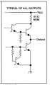
Here is a snip from my circuit simulation (better schematic capture coming soon). The outputs from the AM26C32 would be on the left (labeled A, B, C) and the flip flops are on the right. The 3 10k resistors pull up to 5VDC. Will this work?
(NOTE: The schematic shows AM26LS32A. I think an AM26C32 is a better selection, but would appreciate verification. I might not even need the pullups.)

On the output side, I am using a AM26C31 Differential Line Driver (Datasheet) to drive the signals off the board and into a motor drive. I picked this part because I know it will work with the servo drive encoder inputs. The inputs are connected to the outputs of D-type flip flops (the same CD74AC175 as discussed above). The flip flops have V_OL of 0.5V max and a V_OH of 3.7V min. This seems to play nicely with the AM26C31 V_IL of 0.8V min and V_IH of 2.0V max, so no special interface is needed. Am I correct?
I have a need to mix and match logic families. Just want to make sure I am doing it right.
On my circuit input I have a AM26C32 RS-422 Differential Receiver. This was selected as it is the mating product to the line driver (AM26C31) in the field installed encoder. I believe this has TTL outputs.
The bulk of my circuit uses 74AC series CMOS logic. I need to connect the AM26C32 (Datasheet) to D-Type flip flops CD74AC175 (Datasheet). The concern is that the V_OH (3.8V min) of the AM26C32 is less than the V_IH of the CD74AC175 (3.85V max). I understand this is a common issue with TTL to CMOS and can be solved by installing pullup resistors (10k ohm seeming to be a common value) on the connection between the two chips. I had originally picked out an AM26LS32A which had a much lower V_OH (likely TTL?). I think the AM26C32 (likely CMOS?) might be directly compatible. I'm not great at reading the datasheets but I am getting better.
Here is a snip from my circuit simulation (better schematic capture coming soon). The outputs from the AM26C32 would be on the left (labeled A, B, C) and the flip flops are on the right. The 3 10k resistors pull up to 5VDC. Will this work?
(NOTE: The schematic shows AM26LS32A. I think an AM26C32 is a better selection, but would appreciate verification. I might not even need the pullups.)
On the output side, I am using a AM26C31 Differential Line Driver (Datasheet) to drive the signals off the board and into a motor drive. I picked this part because I know it will work with the servo drive encoder inputs. The inputs are connected to the outputs of D-type flip flops (the same CD74AC175 as discussed above). The flip flops have V_OL of 0.5V max and a V_OH of 3.7V min. This seems to play nicely with the AM26C31 V_IL of 0.8V min and V_IH of 2.0V max, so no special interface is needed. Am I correct?
Attachments
-
 12.1 KB Views: 2


")


