Mixing and amplifying multiple audio signals of various voltages and offsets

Thread Starter

Jordan4501

Joined Sep 26, 2012
11
Hi everyone,

So, first time posting here and first time designing a circuit of this complexity, so I know it's a hot mess but would love some advice. Part names refer to the attached schematic.

I have three audio signals:
Source 1 (J1): mono, 0 ± 2.5V
Source 2 (J2): mono, 0 ± 7.5V
Source 3 (J3 - left, and J4 - right): stereo, 0 ± 0.25V

That I need to mix into two outputs:
Output 1 (J6): combination of Source 1 and Source 2, 0 ± 7.5V, driving a low-impedance speaker
Output 2 (J5): combination of all sources, 0 ± 7.5V, driving a high-impedance device (a wireless transmitter)

I would like to be able to adjust the relative volumes of each source, as well as the output volume of the speaker relative to the wireless transmitter. So, here is the plan:
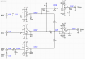
  • remove the DC offset from Source 1 using an AC coupling circuit (R1 and C1)
  • passively sum the left and right channels of Source 3 to turn it from stereo into mono (R6 and R7)
  • use a general-purpose op-amp on each source that (a) brings it up to 0 ± 7.5V and (b) allows variable gain (so the output of each op-amp should range from 0 ± 0V to 0 ± 7.5V) (O1, O2, and O3)
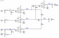
  • passively mix the op-amp outputs from source 1 (output of O1) and source 2 (output of O2) using two resistors (R14 and R15), feed those into a power op-amp, use the output from that to drive the low-impedance speaker
  • passively mix the op-amp outputs from all sources (outputs of O1, O2, and O3) using three resistors (R10, R11, and R12), feed that directly into the high-impedance output (doesn't need a power amp since high-impedance)
In the schematic, the blue text shows what I expect (i.e. what I want) the voltage levels to be at that point in the circuit. With that in mind, some questions about this schematic:
  1. Does this plan make any sense, or is it completely insane?
  2. What should the value of C1 be (AC coupling circuit on Source 1)?
  3. Do the resistor values all look roughly correct?
  4. Is this a logical way to use the op-amps (inverted)? I thought it made sense because I'd like the gain to range from 0 - Rf/Rin.
  5. Does inverting an audio signal really affect the sound quality at all? I know that speakers are usually polarized, so I would assume so. The low impedance output should be the right polarity (two inverting amps in sequence), but the high-impedance one would be flipped.
Thanks!
 

Attachments

Last edited:

crutschow

Joined Mar 14, 2008
34,473
The circuit will basically function, but needs some significant tweaking to get the gain values you want.

  • The LM358 is a noisy op amp with crossover distortion and not well suited to audio use. You should use a lower noise device such as a TL074 or MC34074.
  • R1 has little effect on the input impedance, which is mainly determined by R2 going to the op amp virtual ground so can be eliminated.
  • C1 should be ≥2.4μF for response down to 20Hz (for R2 = 3.3kΩ).
  • R13 should be zero ohms, and R14 & R15 should be 10kΩ for a gain of 1 for U1.
  • R10, R11, and R12 act as attenuators (voltage dividers) for the J5 output. Since the op amp outputs are very low impedance, the load for each 100k resistors looks like two 100k resistors in parallel, or 50k. The attenuation is thus 50k/150k or 1/3, giving a max output of 7.5/3 = 2.5V at J5 (assuming the load at J5 is infinite). If you want 7.5V you will need to add another op amp (which is available if you are using a quad op amp).
  • O3 needs a gain of 30 to amplify 0.25V to 7.5V. For this you can eliminate, R8 (which does noting since it's so much smaller than R6 and R7), reduce R6 and R7 to 10kΩ, and increase pot R9 to 300kΩ.
  • Polarity doesn't matter expect for stereo signals.
Basically you seem to not quite understand how resistors combine in series and parallel. You are ignoring resistors in series/parallel and treating them as separate entities, but their resistances combine with connected resistors into one equivalent resistance.
Suggest you do a little further study on series and parallel resistor circuits. ;)
 
Last edited:

Thread Starter

Jordan4501

Joined Sep 26, 2012
11
Suggest you do a little further study on series and parallel resistor circuits. ;)
Yep, deserved that one. Thank you though, your post was extremely helpful. I do understand the basics of resistor circuits (or at least, I did 8 years ago when I was doing this stuff in Physics II in university), but have never really used them with op-amps so that's throwing me off a bit.

I cleaned up the schematic (attached). A couple questions on this:
  1. For R1 (on O4, note that the original R1 is gone), I think 10K is the right value (after changing R10/R11/R12 to 10K)? Since with 3x 10K resistors in parallel before it, would be equivalent to 3.3K and I want 3x gain.
  2. Are there any downsides of going with an oversized cap for C1? You said 2.4uF, and I know if I went lower I would lose low frequency response, but what if I stuck a 1mF cap in there or something?
  3. Is the LM675 a decent power amp for audio, or would you recommend replacing that with something else as well? For an unrelated project, is there an audio-grade power amp that comes in a quad package that you would recommend?
Thanks again!
 

Attachments

crutschow

Joined Mar 14, 2008
34,473
1. 10k for R1 should be fine.
A nit but the voltage at the O4 negative input is always essentially zero since it is a summing junction.
2. You can oversize C1 if like but 1 mF is rather overkill. It may give a long startup transient.
3. The LM675 is only stable with a gain of ≥10 so it won't work if you want a gain less than that.
You could run it at a fixed gain of +10 (non-inverting) and use a pot at the input to control the voltage.
I'm not that familiar with audio power amps so can't really help you with an alternative.

Here are quad audio amps.
 

ebeowulf17

Joined Aug 12, 2014
3,307
I would never discourage anyone from doing a project like this for fun, education, or sense of accomplishment. Having said that, if you just need the audio processing to get done, there are relatively affordable audio mixers that will do all of this easily.

Unless this is part of a larger project that already covers some of these things, providing a power supply, housing, input/output jacks, etc. will eat up a significant portion of your budget before you even get to the components shown in your schematic. Depending on what your time is worth, it may be cost effective to simply buy a mixer. They also offer extra features like EQ and headphone jacks which may or may not be any benefit to you.

Here are two examples:
https://www.sweetwater.com/store/detail/Mix8

https://www.sweetwater.com/store/detail/802--behringer-xenyx-802-mixer
 

Thread Starter

Jordan4501

Joined Sep 26, 2012
11
3. The LM675 is only stable with a gain of ≥10 so it won't work if you want a gain less than that.
You could run it at a fixed gain of +10 (non-inverting) and use a pot at the input to control the voltage.
Any particular reason you suggest non-inverting instead of inverting?

I would never discourage anyone from doing a project like this for fun, education, or sense of accomplishment. Having said that, if you just need the audio processing to get done, there are relatively affordable audio mixers that will do all of this easily.
This is actually for a specialized application in a vehicle in a confined space, so an off-the-shelf mixer doesn't really work. This does bring up the question though: since my power supply is +11 to +14.5 V (depending on if vehicle is running, other loads, etc.), is this fluctuation in the +/- op-amp rails (I'm using a 12V DC-DC converter to get the -12V) going to have a major impact on audio quality? Do I need to filter the power supply somehow?

Talking about the summing junctions again, I'm a little confused on one aspect of it:

  • R10, R11, and R12 act as attenuators (voltage dividers) for the J5 output. Since the op amp outputs are very low impedance, the load for each 100k resistors looks like two 100k resistors in parallel, or 50k. The attenuation is thus 50k/150k or 1/3, giving a max output of 7.5/3 = 2.5V at J5 (assuming the load at J5 is infinite). If you want 7.5V you will need to add another op amp (which is available if you are using a quad op amp).
When you say this, doesn't this assume that only one of the op-amps is providing any output and the other two are almost like a ground, hence the voltage divider? What if all three sources/op-amps are "on" and O1, O2, and O3 are all outputing 7.5V at a given instant? Then the voltage at the summing junction would surely be 7.5V, not 2.5V? And if that does happen, and O4 has a gain of 3x, then I would be trying to amplify it to 22.5V using 12V rails?
 

crutschow

Joined Mar 14, 2008
34,473
Any particular reason you suggest non-inverting instead of inverting?
Makes it easier to use a pot on the input to control the output gain from 0 to max without the amp gain ever going below 10.
When you say this, doesn't this assume that only one of the op-amps is providing any output and the other two are almost like a ground, hence the voltage divider?
Yes.
But all outputs have a very low impedance AC ground, so each output sees the other two resistors as a divider to ground.
And yes, if you have more than one output at the same time then they sum together based upon the attenuation of the resistors.
 
Last edited:

crutschow

Joined Mar 14, 2008
34,473
is this fluctuation in the +/- op-amp rails (I'm using a 12V DC-DC converter to get the -12V) going to have a major impact on audio quality? Do I need to filter the power supply somehow?
Yes.
Generally only high frequency noise is of concern, not slow voltage fluctuations, so it's standard practice to decouple all amps with their own 0.1μF ceramic caps directly between each power pin and ground (2 caps for each amp), along with a 10-100μF electrolytic cap from each power rail to ground (2 total).
That will minimize any power supply noise getting into the audio.
 

Thread Starter

Jordan4501

Joined Sep 26, 2012
11
Alright, I've implemented all this advice into the new schematic (attached).

I think I did the calculations right for the voltage divider at R13/R14/R15 with the goal of dropping the signal down to 1/10th (±0.75V), so that the LM675 at 10x will bring it back up to the desired ±7.5V. Pot R8 is the volume control (0 to 7.5V), going into U1 which amplifies by 10x (1 + 10K/1.1K).

I added the caps to each each op-amp's power pins (is this what you meant?), although a little confused on that one. If each amp gets a 0.1uF cap on each power pin to ground, but all the amps' power pins are connected to the same rails, isn't this the same as having 5x 0.1uF caps in parallel, which would be equivalent to having a single 0.5uF cap from each rail to ground? Or perhaps it has to do with the physical distance between the 0.1uF cap and the amp's power pin?

For the 100uF electrolytic for the -12V rail to ground, should the negative pin on the cap go to -12V or to ground?
 

Attachments

crutschow

Joined Mar 14, 2008
34,473
Alright, I've implemented all this advice into the new schematic
I didn't check the values, but the schematic looks okay now.
Or perhaps it has to do with the physical distance between the 0.1uF cap and the amp's power pin?
Yes.
Even a short piece of wire can have significant inductive reactance at high frequencies which prevents the capacitor from doing its proper filtering job.
For the 100uF electrolytic for the -12V rail to ground, should the negative pin on the cap go to -12V or to ground?
The capacitor negative pin always goes to the most negative voltage and that would be -12V with respect to ground.
 

Thread Starter

Jordan4501

Joined Sep 26, 2012
11
Thank you, you've been an amazing help! Just one more question: if I'm using a quad-package for the op-amps (so there are only two power pins for 4 amps), should I still use a 0.1uF cap on each pin or a 0.4uF cap? Also, does the 0.1uF decoupling cap apply for the LM675 as well as the TL074s?
 
Last edited:
Top