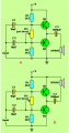
Your second circuit does not have bootstrapping like mine does.
For an output of 4W RMS into 8 ohms then the speaker peak current is 1A.
BD135 and BD136 transistors have a minimum current gain of almost nothing at 1A so the base current from the driver transistor must be hundreds of mA.
Instead if you use TIP31 and TIP32 (or TIP41 and TIP42) output transistors then their minimum current gain of 25 at 1A need a current of 40mA from a driver transistor which can be a little 2N4401 or 2N2222A.
Power amplifiers have not used input coupling capacitors like you show for about 57 years. Instead they are DC-coupled and have plenty of negative AC and DC feedback.
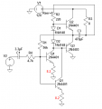
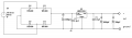
this is the schematic, with 5W into 8ohms..
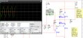
probe 3 shows voltages and currents for the 2n4401..
will there b a problem??
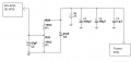
i also attached my idea about the power supply, 24 V for the PA and 12V to other parts of the circuit..
but i want to use only one supply in actual..is it alright to use voltage divider?what do you think of the values?
You cannot power anything with a voltage divider because its voltage drops when it has a load. A voltage divider is used to provide a low current reference voltage like to an opamp that has an extremely low input current.
Your supply is 24V again?
Without a signal, the driver transistor has a current of 47.3mA and it has a collector voltage of about 12.2V. Then its heating is 47.3mA x 12.2V= 577mW which is close to its max allowed heating of 625mw when it is in free air. It gets hotter when it drives the PNP output transistor.
Be a smarty ass and use two 2N4401 or 2N2222A transistors in parallel to share the heat. Each one needs an emitter resistor of about 8.2 ohms so that they share the current equally. The resistors cause a small output power reduction.
With a 12V supply, you get about 10.5V p-p into 8 ohms. My simulation gets 10.5V p-p.
10.5V p-p/2.828= 3.71V RMS. (3.71V x 3.71V)/8= 1.72W.
If you blast the input signal at a high level then the amplifier output clips very badly making a squarewave then the output power has 1.72W for the fundamental plus another 1.72W for the harmonics.
Your circuit has a maximum current of about 400mA at 18V. The diodes are rated for 1000mA so they will be pretty warm but not hot.
The 7818 will have an input of 23.4V so it will dissipate (23.4V - 18V) x 400mA= 2.16W. It will also be pretty warm but not hot.
The fuse should be in series with the 230V or 110V hot primary wire. The circuit uses about 10W so the primary current is 44mA at 230V or 91mA at 110V. Use a 0.1A fuse for 230V mains and use a 1/4A fuse for 110V mains. Use a slow-blow fuse.
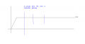
when i simulated the power supple, i forgot to tell you that i tried viewing its wave on the oscilloscope, but the wave, which is a straight line at 18.0001Vdc, seems to have a pause at some times.
Why do you have 1000uF and 100uF at the output of the 7818 regulator? The datasheet shows only one 0.1uF ceramic disc capacitor.
The regulator regulates the output voltage so the high value capacitors are not needed if the regulator maximum output current is high enough to power your circuits.
What is a "source"?
The output of the LM7818 regulator needs a 0.1uF ceramic disc capacitor to ground. It does not need 1000uF and it does not need 100uF.
The LM7818 has a maximum output current of 2.2A if it is not too hot. Then its input current is 2.208A.
If your amplifier draws only 60mA when it is without a signal then the current from the voltage regulator is only 60mA. If your amplifier draws 400mA when it is playing loudly then the current from the voltage regulator is 400mA.

 Facebook
 Google
 GitHub
 Linkedin