Mixer and Power Amplifiers

Thread Starter

creaver31

Joined Feb 2, 2012
65
ahh see, haha i thought it will provide constant current.. so i'll use a 18V 1A transformer.. i'll put a 1.5A fuse in series with the output of transformer before the rectifier diodes right? and a switch at the input of the transformer..


another question,, what is the normal output signal of a mp3 player or an ipod?,, i'll use the line-ins for the mp3 player or ipod.
 

Audioguru

Joined Dec 20, 2007
11,248
i'll use a 18V 1A transformer.. i'll put a 1.5A fuse in series with the output of transformer before the rectifier diodes right? and a switch at the input of the transformer.
No.
the fuse should be on the high voltage primary side of the transformer in series with the switch. Calculate the rating of the fuse since its value is much less.

what is the normal output signal of a mp3 player or an ipod? I'll use the line-ins for the mp3 player or ipod.
The line OUTPUTs (not inputs) of an MP3 player or ipod is about 200mV RMS when it is loud.
 

Thread Starter

creaver31

Joined Feb 2, 2012
65
thanks, about the power supply, it is a single supply right? so the other end is 18V and the other is 0V, which is also the ground?

haha just making sure cuz' we're soldering parts now to the PCB :D
 

Audioguru

Joined Dec 20, 2007
11,248
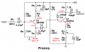
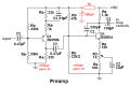
The voltage divider biasing the first transistor in the mic preamp feeds any hum and noise on the power supply into the input of the preamp. An RC filter will prevent power supply noise from being amplified.

The power amplifier has different transistors that we last talked about. It might oscillate at a high frequency which will make the transistors very hot. Try adding a small value capacitor (47pF to 330pF) between the base and collector of the driver transistor.

Don't make it on a breadboard.

I checked the DC voltages of the preamp. The second transistor will have a low maximum output swing:
 

Attachments

Thread Starter

creaver31

Joined Feb 2, 2012
65
so i'll just add a 620 ohm resistor to the input to reduce hum and noise,
are the values of resistors in the mixer okay?
 

Thread Starter

creaver31

Joined Feb 2, 2012
65
The voltage divider biasing the first transistor in the mic preamp feeds any hum and noise on the power supply into the input of the preamp. An RC filter will prevent power supply noise from being amplified.

The power amplifier has different transistors that we last talked about. It might oscillate at a high frequency which will make the transistors very hot. Try adding a small value capacitor (47pF to 330pF) between the base and collector of the driver transistor.

Don't make it on a breadboard.

I checked the DC voltages of the preamp. The second transistor will have a low maximum output swing:
is that ok? or do i need to change my biasing?
 

Thread Starter

creaver31

Joined Feb 2, 2012
65
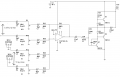
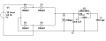
here is the schematic of my power supply and mixer to power amp..

in the power supply, i'll put the fuse in series with switch before the transformer, right?

please check my mixer to PA schematic :D
 

Attachments

Audioguru

Joined Dec 20, 2007
11,248
so how can i do that? you said about RC filter, isn't that for frequency?
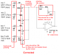
If the power supply has hum and noise then your base voltage divider for the first transistor in your preamp feeds the hum and noise directly into the first transistor.
You need a series resistor then a capacitor to ground as a filter for the supply voltage that feeds the first transistor.

Since you use a PNP transistor then its emitter is bouncing up and down with the hum and noise from the power supply and is amplifying it. Then the RC filter must feed the entire first transistor circuit and the voltage divider for the second transistor like this:
 

Attachments

Audioguru

Joined Dec 20, 2007
11,248
Your mixer, power amp and power supply look good.:)
Did the 330pF capacitor across the driver transistor cool it? 330pF is a fairly high value that might reduce high audio frequencies. I did not simulate it but you should hear if it cuts high frequencies.

Some of your resistor values are odd. 8.6k??
8.2k and 9.1k are standard values.

I have used 5% resistors for about 44 years. Before that I used 10% resistors.
You should study a list of resistor values that are available in your country and use them.
 

Audioguru

Joined Dec 20, 2007
11,248
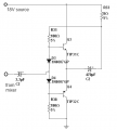
The new current amplifier has no negative feedback so it will have distortion.
It has no voltage gain and actually has some signal voltage loss.
Its input resistance is less than 180 ohms which is much too low to be driven from your mixer opamp.

Why did you remove the driver transistor and remove the negative feedback?
 

Thread Starter

creaver31

Joined Feb 2, 2012
65
Why did you remove the driver transistor and remove the negative feedback?
i just saw this configuration on my book.. whew i guess i should have bought other books,

what happens if there is no driver transistor? is there really no gain?
i am just worried that the driver transistor will be melted again hahaha..

could you help me on my design? just a replacement in case of a problem.
 

Audioguru

Joined Dec 20, 2007
11,248
If the driver transistor has a small capacitor (47pf to 330pF) from its base to its collector then it cannot oscillate at a high frequency which will make it hot.

With no signal, the collector voltage of the driver transistor is 8.7V and the 220 ohm collector resistor has 7.4V across it so its current is 33.6mA.
Then the heating of the driver transistor is 8.7V x 33.6mA= 0.29W which is low.

When the amplifier is working hard then the driver transistor has an additional average collector current of about 18mA for the base current of the PNP output transistor so its total current is 33.6mA + 18mA= 51.6mA. Then its heating is 8.7V x 51.6mA= 449mW which will make a little 2N4401 fairly hot and make a BD135 very warm but not too hot.

The output transistors are emitter-followers that have no voltage gain and actually have a small signal voltage loss.
All the voltage gain in your complete amplifier comes from its driver transistor. It has bootstrapping so its collector swings about 16V p-p.
The driver transistor can provide the necessary current in the 220 ohm collector resistor plus the base current for the PNP output transistor.
 

Thread Starter

creaver31

Joined Feb 2, 2012
65
ahh see, so i really need the driver transistor.. and i'll use BD135 to avoid too much heating.. about the diodes, if i use 1n5400, which is a little larger than 1n4007, do is still need to clamp it to a heat sink?
 
Top