Misting Controller repair

Thread Starter

dendad

Joined Feb 20, 2016
4,479
As this may be of interest to some folk, here is a repair I've just done.
I was approached recently to try to fix a Watermatic Misting Controller.
Photo on 12-12-18 at 09.44 #3.jpg
This is a good example of what something like an Arduino could do. In fact, the customer is after more so I am going to encourage them have a try at doing their own based around Arduinos.


Photo on 12-12-18 at 09.43.jpg
The main problem was corrosion on a couple of tracks.

The build is a bit "agricultural".


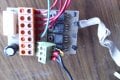
I spent quite while trying to trace the circuit so as to try to figure out how it works. And this circuit may well have errors.
circuit.jpg

This sort of circuit brings back memories of some of the things I have built in the past. Thank God for micro controllers!
 

Attachments

LesJones

Joined Jan 8, 2017
4,191
Hi dendad,
I have built something similar using a PIC16F88. It is a 4 channel sequencer for driving solenoid valves. It uses 4 pots to set the individual channel times by feeding the output from the slider on each pot into a channel of the ADC. The value read controls the number of times a delay routine is called in the timing of each channel. I was going to post the schematic but I found that I had not bothered drawing one as it was so simple. If it is any interest to you I can draw the schematic and post the source code which could be modified to do exactly what your unit does.

Les.
 

Thread Starter

dendad

Joined Feb 20, 2016
4,479
Hi dendad,
I have built something similar using a PIC16F88. It is a 4 channel sequencer for driving solenoid valves. It uses 4 pots to set the individual channel times by feeding the output from the slider on each pot into a channel of the ADC. The value read controls the number of times a delay routine is called in the timing of each channel. I was going to post the schematic but I found that I had not bothered drawing one as it was so simple. If it is any interest to you I can draw the schematic and post the source code which could be modified to do exactly what your unit does.

Les.
Thanks Les but it will be ok. I just posted this to reminisce what things were like years ago. I too would use a microcontroller to do this job. It is SO much simpler!
Likewise, I often draw PCBs and not the circuit as that is easy but then have to go back and do the circuit to complete the documentation.
 

Thread Starter

dendad

Joined Feb 20, 2016
4,479
What was the nature of the repair?
If you look at the 3rd picture there is a blue wire under the board. That track was corroded.
Also, the ribbon cable had been pinched as the board was screwed down into the case. My test "solenoids" were bidirectional LEDs with 2K2 series resistors and the TRIACs switched them in sequence so I think it is working as it should now. One of the problems with fixing something like this is trying to determine what it does anyway. Spending the time to trace the circuit helped a lot.
If I was doing this for a living and not mainly just for interest sake, this repair would not by economic as the time spent was pretty excessive. But it was interesting and worth the effort.
 
Top