 Facebook
 Google
 GitHub
 Linkedin
Hi, I've just joined AAC and this is my first post.
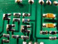
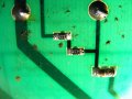
I'm currently attempting to reverse engineer a circuit board in order to create a circuit diagram. On the PCB there are many standard components I recognize but also many miniature ones that I have no experience of. I would therefore appreciate if someone could clarify why they are used along side standard size components, and also how to correctly identify:-
a, What they are (resister, capacitor or diode)?
b, What their values are?
c, Polarity?
Using a magnifying glass and checking across the connections with an Ohmmeter, the values on the black components in the pictures tie up with their metered values, albeit they are still in circuit and therefore might be influenced by other components. But mainly why these tiny components are used in the first place and where I could read the why's and therefore's on them?
Many thanks
Attachments
-
 42.2 KB Views: 11
 -
 30.7 KB Views: 11
") Also, because they cost a lot less to make and install.
Also, because they cost a lot less to make and install.


