Facebook
 Google
 GitHub
 Linkedin

First of all.
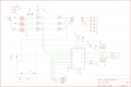
There are few component value errors on the schema. Will correct them as per the prototype.
Just finished the PSU regulator PCB and the Driver.

The Regulators. I am using a LM317T to get the Aux 12V rated at 1.5A.
For the 5V, I am using a sanken 5V switching Reg. rated at 3.5A.
Plenty to go around.
The supply Reg's are working, for the time being I will be using my Big daddy PSU to get the 24VDC.

The Driver I prototyped. Haven't tested it yet, fuses are not yet installed. But will be tested with them.
I got a little confused abt the NFB resistors, some doc's say that it shud be a non inductive type. Ran around whole night to get the value for 3 Amps, which if my calculation is correct rounds up to 0.17Ω at 2W.
I ended up with nichrome wire, since I have a mili ohmmeter. It was easy to cut the value.. I labeled the NFB. I hope this works.
Will update after testing.....
There are few component value errors on the schema. Will correct them as per the prototype.
Just finished the PSU regulator PCB and the Driver.
The Regulators. I am using a LM317T to get the Aux 12V rated at 1.5A.
For the 5V, I am using a sanken 5V switching Reg. rated at 3.5A.
Plenty to go around.
The supply Reg's are working, for the time being I will be using my Big daddy PSU to get the 24VDC.
The Driver I prototyped. Haven't tested it yet, fuses are not yet installed. But will be tested with them.
I got a little confused abt the NFB resistors, some doc's say that it shud be a non inductive type. Ran around whole night to get the value for 3 Amps, which if my calculation is correct rounds up to 0.17Ω at 2W.
I ended up with nichrome wire, since I have a mili ohmmeter. It was easy to cut the value.. I labeled the NFB. I hope this works.
Will update after testing.....