Mini Engraver

Thread Starter

R!f@@

Joined Apr 2, 2009
10,007
First of all.
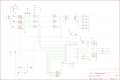
There are few component value errors on the schema. Will correct them as per the prototype.

Just finished the PSU regulator PCB and the Driver.


The Regulators. I am using a LM317T to get the Aux 12V rated at 1.5A.
For the 5V, I am using a sanken 5V switching Reg. rated at 3.5A.
Plenty to go around.
The supply Reg's are working, for the time being I will be using my Big daddy PSU to get the 24VDC. :D


The Driver I prototyped. Haven't tested it yet, fuses are not yet installed. But will be tested with them.

I got a little confused abt the NFB resistors, some doc's say that it shud be a non inductive type. Ran around whole night to get the value for 3 Amps, which if my calculation is correct rounds up to 0.17Ω at 2W.

I ended up with nichrome wire, since I have a mili ohmmeter. It was easy to cut the value.. I labeled the NFB. I hope this works.

Will update after testing.....
 

Thread Starter

R!f@@

Joined Apr 2, 2009
10,007
Hey guys.
What would be the max ratings for 24V supply to continuously operate the for axis excluding the spindle.

I like to get a PSU but I have no idea on the max power rating
 

SgtWookie

Joined Jul 17, 2007
22,230
Not complete malarkey.

Choosing diodes that are rated for higher current than you are expecting will result in a lower Vf, thus a lower power dissipation across the diodes.

Schottky diodes have the lowest Vf. You can de-rate them and get a much lower Vf across them.

Just look at the cost and time lag for your drivers, and look at the cost for the rectifiers. Rectifiers are cheap.

You don't want to blow your drivers. If you can spend an extra dollar to protect that investment, it's worthwhile.

Meanwhile, unless that aluminum angle is water-cooled, you probably don't have sufficient cooling - and will smoke them anyway.

Look man, don't be stupid about this. I told you that you needed very good heat sinking from the beginning. Aluminum is not a great heat sink; it's only about 59% as effective as copper, and about 30% as effective as water.
 

Thread Starter

R!f@@

Joined Apr 2, 2009
10,007
Retched is holding my package. He has bought all the PIC's that I you guys had suggested and have pickit3 for me.
Since Sgt suggested that having protection diodes is worth it, I asked retched to find some. He suggested PIV 50V, 3A diodes. But he also did not say anything about the no. so I cannot check on data.
That is why I asked for a number that goes with the TB6560.
Is the data that is given above sufficient for protection diodes. retched said he inquired abt schottky diodes.

What are the current rating that I suggest.
What Alberto suggested was T0-220 package. and is rated at 20Amps, PIV 100V.

I can only cope with through hole types for now.

As for heat sinking, I have aluminum heat sinks. I said I will keep in mind how hot the IC gets. If it is too much I can use bigger ones. Forced Air cooling can be done. Water cooling can be done if it comes to that. Cause I have done water cooling for a graphics using copper pipes. Heat is not the issue for now. I will deal with it once the motor is in operation.

So just advice on a number that is sufficient for me.
 

BMorse

Joined Sep 26, 2009
2,675
mind showing me how you did that..

I do not have pics of the assembly, but I can take some and post them on here so others can also get an idea on how to fabricate their own......

This spindle is meant to be belt driven by a high torque Variable speed motor,
Basically the body of it is machined (I ran it on the lathe at the shop) and hollowed out, both ends are recessed in so the bearings can be pressed in on each end, the main shaft is machined out of some hardened tool steel (was hardened after the machining was done), the end does not have a chuck, but has been machined to fit a standard 1/8" shaft tooling and the bit is held in place with a set screw....... I will get the pics done so it will be easier to understand than me trying to explain it....:D
 

shortbus

Joined Sep 30, 2009
10,049
R!f@@ - you have to watch using the TB6560 chips. I don't remember it all, but its something about how it is powered-up. If the step and direction pins are accessed before the power sequence is complete the chip smokes. If you go to CNCZone.com and search for TB6560 it will give a bunch of hits on the problems people have with the chip.
 

t06afre

Joined May 11, 2009
5,934
OK, this is what I got so far. There is something I didn't understand regarding TB6560s PIN 17 and 19, and the BC557 transistors... Need some guidance there.
What is the source of your schematic Jens. Is it from some application note. It looks kind of starnge to me
 
Top