Mini Engraver

SgtWookie

Joined Jul 17, 2007
22,230
Good deal, Rifaa!

Make sure to read the Usage Considerations (attached) before you start designing your board. Pay particular attention to the fusing and heat sinking requirements. If you don't stay within the allowable operating range of the IC, you will fry it very quickly.
 

Attachments

Thread Starter

R!f@@

Joined Apr 2, 2009
10,007
Good deal, Rifaa!

Make sure to read the Usage Considerations (attached) before you start designing your board. Pay particular attention to the fusing and heat sinking requirements. If you don't stay within the allowable operating range of the IC, you will fry it very quickly.
Will do, Still waiting to see what BMorse likes to add.
 

Thread Starter

R!f@@

Joined Apr 2, 2009
10,007
Sorry R!f@@, that what you saw was spam.
I removed it.

Excuse me :confused:
 
Last edited by a moderator:

BMorse

Joined Sep 26, 2009
2,675
Will do, Still waiting to see what BMorse likes to add.

Sarge pretty much covered it, you have the drivers and the motors so we are looking forward to what you come up with in regards to controlling these motors.... just follow the general guidelines in the datasheet for the drivers and you should be ok...


B. Morse
 

Thread Starter

R!f@@

Joined Apr 2, 2009
10,007
Sarge pretty much covered it, you have the drivers and the motors so we are looking forward to what you come up with in regards to controlling these motors.... just follow the general guidelines in the datasheet for the drivers and you should be ok...


B. Morse
Oki Doki. let's see what I can cook up.
 

Thread Starter

R!f@@

Joined Apr 2, 2009
10,007
One more thing...
What is the preferable Spindle/router RPM ? like 2000rpm or 2600rpm...
Should the Spindle/router motor need to be high torque or would low torque suffice?
 

BMorse

Joined Sep 26, 2009
2,675
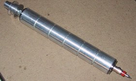
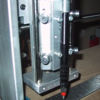
Spindle speed should be adjustable from 2000 to 30,000+, currently I am still using a dremmel with variable speed (5,000 to 30,000)on it, so it makes it easy to slow it down when cutting plastics (Or the plastic will heat up and melt to the milling bit), and some times I run it on max speed when milling PCB's (30,000 RPM), plus High torque, you do not want the spindle to get stuck if the bit bites into more material than what it can handle to remove, the spindle has to be able to overcome this.....

B. Morse
 

BMorse

Joined Sep 26, 2009
2,675
I tested by dremel for speed and am surprised to see that it goes up to 30,000 rpm

Yeah, that is the maximum speed for most rotary tools such as a dremmel. I am looking for one that can go beyond that, to maybe 45,000, but I am having a hard time finding such a tool, so I may get around in finishing my own design for a high speed spindle assembly, just have to find the right motor and speed controller to work with my spindle....


But for now the flex-shaft attachment for the dremmel works really good for the meantime...


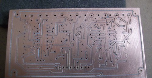
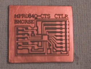
the flex attachment hardly has any play on the end so you can actually do some pretty elaborate PCB's with it...


16 pad QFN package


B. Morse
 

Thread Starter

R!f@@

Joined Apr 2, 2009
10,007
U know u are making me jealous by showing pictures of ur work :).
I always wanted to make PCB like that ever since I started working.

I have seen motor that go beyond 30,000 rpm in some web site. I googled and came up with precision spindle and motor makers that u can demand.
I believe this was the site.

http://www.spindlesworld.com/

I am being restless now that I am acquiring parts to complete my machine

U said that I won't need a μC but the PC will do.
So what I need is to make the drivers using the TB6560 IC's that I have.
Is this right, I thought this is so.

So, I tried to find schema's using this and all I can find are complete boards.
I do not need complete boards now that I have the chips. I can get a friend to etch the boards is I can get my hands on a schema.

Will the PC be responsible for generating the necessary timing signals for the chip via LPT. I this is the case then can I use the LPT interface board that the seller gave me.

Another problem is the steppers do not trn free hand. I mean I can turn the shaft by hand. So I took em apart ad re-assembled them. Now I can turn them by hand, is this an issue?

The shaft is round, should it not have a flat side so the coupling can be screwed so that it won't slip?

I need somebody to suggest me a way to make the stepper drivers, what should be included and not included.
By this I mean how the control inputs be left. Should they be connected to the interface board I have or should there be any circuit in between to take care of the power on sequence of the driver as said in the design consideration.

Further more from the boards that I have seen, there are dip switches to control the step and the likes. Are these necessary if a PC is used to control the stepping and speed sequences.

problem is the design consideration sgt suggested, it shows a μC connected and switching timings.

How is this possible using ur PC.
I am rather confused by now in what I should make.
A PCB without a μC interface.

By the way B, the site I suggested makes VFD together with the desired high rpm low noise motors too
 

BMorse

Joined Sep 26, 2009
2,675
basically any stepper motor controller that accepts logic inputs to control the step and direction of the motor would work with the parallel port, weather this motor controller is uc based or discrete parts based it does not matter as long as it has TTL logic inputs for the direction and motor step control....
 

shortbus

Joined Sep 30, 2009
10,049
Quote Rifaa: " Another problem is the steppers do not trn free hand. I mean I can turn the shaft by hand. So I took em apart ad re-assembled them. Now I can turn them by hand, is this an issue? "

You may have ruined your steppers! They are aligned internally when manufactured and are not supposed to be disassembled. That is the commonly held opinion anyway.
 

Thread Starter

R!f@@

Joined Apr 2, 2009
10,007
It's that I can turn one quite easily but not the others. So after taking them apart I saw the internal spring washers are placed at different location from motor to motor, so I placed them the same way. Now all of em turns quite easily I must say.

If I ruined it I have to build a driver to test em. I reckon I can align them If some one tells me how they should behave.

I downloaded the Mach Version R3.042.040.
Just like to know if this is the right software.

I like some one to direct me the right way to test a stepper once I got it hooked to LPT after building the driver.

I got a a nice schema from CNC Zone for my TB6560. After the OP gives me permission I can post my modifications.
So after building this I like to test the motors.
 

Thread Starter

R!f@@

Joined Apr 2, 2009
10,007
Before I go on buyin any thing else I thought of testing the motors.
So now I am working on just one driver on vero board.

But All the components will be same as for the original Axis drivers.

Will post the results and a schema ones completed.

I have seen schema's with fuse ratings as much as 6.5A for a TB6560.
According to the data it should be 3A.
I like to make sure that my conclusion abt fuse rating per TB6560 is correct.
I have placed a fast blow 3A in the High voltage line.

The HV should not go beyond 30V as I have read, I have 24V in mind.
One q? though. What should be the power rating of the complete supply for the axis controllers.
I like to know what you guys are using, giving me a figure will be helpful

Been thinking and reading. it says 3.5A per phase, to be on the safe side it's 3A, so with two phase it should be 6A. For the fuse to stay on without nuisance blowing 6.5A.
Is this so?
 
Last edited:

SgtWookie

Joined Jul 17, 2007
22,230
I'd fuse each phase at 3A. You don't want the current per phase to go over that, even for a moment. Remember the applications guide I posted?

Better read through it again if you have any doubts at all.

Also, don't even apply power to the driver unless it has a large heat sink properly attached. People have fried those IC's in seconds; because they didn't pay attention to the cautions and warnings.
 

Thread Starter

R!f@@

Joined Apr 2, 2009
10,007
The design guide plus the peliminary data sheet are the two documents I am going thru continuously.

The IC is mounted an adequate heat sink and I will check the temp rise when testing

Sgt
U said 3A per phase, so the main supply line will be at 6A minimum.

As for frying, I bought 7 pcs. Just in case. :D.

Few question though.
The optos' used for isolation, I have seen diagrams using different types.
Is the operating frequency a primary concern when using opto's.

Second, the data sheets for TB6560AHG specifically says it does not need External schottky barrier diodes.
Page 14 first table, last row - Design consideration guide

From this I assume that these a back EMF clamping diodes.
Or are they?
Cause I am having hard time to find diodes from my junk. :confused:
 

Attachments

SgtWookie

Joined Jul 17, 2007
22,230
The design guide plus the peliminary data sheet are the two documents I am going thru continuously.

The IC is mounted an adequate heat sink and I will check the temp rise when testing.
OK, that's all good.

You said 3A per phase, so the main supply line will be at 6A minimum.
Yep. You could fuse the main line too, if you'd like.
As for frying, I bought 7 pcs. Just in case. :D.
Never hurts to have spare parts.

Few question though.
The optos' used for isolation, I have seen diagrams using different types.
Is the operating frequency a primary concern when using opto's.
Yep. You can wind up with a pretty large propagation delay through them. Turn-off times seem to be quite a bit longer than turn-on times.

Second, the data sheets for TB6560AHG specifically says it does not need External schottky barrier diodes.
Page 14 first table, last row - Design consideration guide

From this I assume that these a back EMF clamping diodes.
Or are they?
Cause I am having hard time to find diodes from my junk. :confused:
Yes, they are internal clamping diodes.

I mentioned to use external diodes, because that would help to keep the ICs' package cool. You don't have to if you don't want to. However, since you're operating the IC at it's max, adding external diodes helps to lighten the load on the IC itself. Unless you're using Schottky diodes externally, you wouldn't be helping the situation.

You could always leave pads for them in your board design, and if it proves necessary to add them later, you can do just that without having to make new boards.
 

Thread Starter

R!f@@

Joined Apr 2, 2009
10,007
Here the schema that I am planning to use as my original driver for the stepper.

But now a vero board version is coming up to test the motors.

If you see a problem then let me know ASAP
 
Last edited:
Top