Mini Engraver

Thread Starter

R!f@@

Joined Apr 2, 2009
10,007
It's just like you said BMorse, these kind of things takes time :(.
The problem is the spindle noise, I think I have a suitable motor for that, but it's brushes are broken, I'm having a hard time trying to find it, I think I had order 'em online.
Next is the PSU, it needs a high voltage and I don't have a PSU that could drive it yet, but I am making one now.
You might have seen the transformer I posted. I wanted to built one HV PSU from it, it took a long time to figure out hoe to get the voltage close to 40V.
Just now I finished the circuitry and tested it, I can get 40V. :D

Had a little chat with LChung about load regulation, and I am trying to beat him to it :p.
I tested the PSU amp capacity, I loaded it to 12A at 40V and the transformer is cool, and the series pass transistors also can handle that really well, they does not seem to care to heat up :eek:.

One problem though, when loaded to 12A voltage is sagging too much, so I need to beef up the wiring, so now I am in the process of doing it.

I did had a little trouble with the circuit as it start to oscillate at rather low frequency, had to crack my head to figure out the problem. I made a little mistake in the schema, I have to correct it and re up it. ans a s for the values also will be up loaded with the correction.
I think It's a nice PSU project to add to the forum collection.
A little testing is yet to be done.

BMorse.. you are just like me.... I too don't sleep much.
I guess great minds behave alike...or is it think alike...:D
 

BMorse

Joined Sep 26, 2009
2,675
Here are some other pics of other machinery I am working on right now at the shop....

This one is an AC Motor Trash compactor... first of its kind NOT to use Hydraulics..... I had designed everything from scratch, and it is controlled by a Pic uc.... I designed and fabricated everything including the frame and all the sheet metal panels you see....

View attachment 17221

View attachment 17222

View attachment 17223

This one is part of a lot larger machinery, this is just one of the crusher units I designed for this particular model, this unit takes 1750 RPM's from a 3 phase AC motor and converts the output to 1450 Pounds of torque per square inch....
View attachment 17224

View attachment 17225


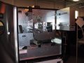
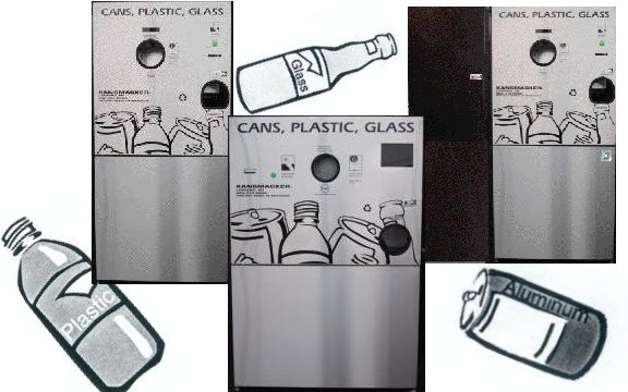
Here is another automated machine.....
Mini3in1.jpg

I have also designed a few other models used all over Michigan and some other states, we currently have around 750 customers just in Michigan alone.... I designed all the hardware, software, and all electronics....


B. Morse
 
Last edited:

Thread Starter

R!f@@

Joined Apr 2, 2009
10,007
I think I just started a trend ;) eh!!

Alberto, nice machine. what is it by the way?
BMorse, that trash compactor is one hell of a machine :)

PS..I wish I had a machine shop....sob :(
 

SgtWookie

Joined Jul 17, 2007
22,230
Well, you need to figure out how much torque you need to accelerate your table.

Convert all of the holding torques to a standard unit for comparison.

Lower voltage units are more attractive. Look for the inductance per winding. The higher the inductance, the longer it will take for current to reach the motor's rated current when supplied by DC. Driving the motor using high voltage and a chopper driver will help decrease that time by quite a bit.

I mistakenly bought some bipolar steppers several years back that are rated for 55v. They were cheap, for good reason. I'd have to run them at 200V or so just to get a halfway decent step rate out of them.

About the same time, I picked up some small steppers rated for 4vdc @ 1.2A/phase. I'll be driving these from some L6258EX microstepping universal motor drivers that ST Microelectronics sent to me as free samples. The motors and drivers would not be adequate for your project, but you have to keep the drivers in mind - what will you be driving these with?

As the power goes up, the cost for the drivers will increase considerably. Once you go beyond a couple of Amperes per phase, you're really looking at using discrete solutions. There are a few H-bridge drivers that exceed that threshold, but you have to be very aware of the heat dissipation issues.

Now, the MSK 3004 that you posted the datasheet for the other day looks quite promising. However, if you wish to get a really fast step rate from your motors, you will need to feed the H-bridge driver with fairly high voltage - less than the 55v max, of course.

Let's say you limited the supply voltage of the 3004 to 48V. The lower the voltage rating of the stepper motor, the more rapidly you could step it using the 48v supply. However, the power dissipation in the H-bridge will increase, as the MOSFETs in the bridge will spend more time in the transition stage; the linear region where they are dissipating power as heat. You need to be able to remove that heat somehow.

I would even consider using water or mineral oil cooling.

The latter (mineral oil cooling) is kind of interesting. At the local college where I'm attending evening courses, they have a computer motherboard and power supply in an acrylic aquarium filled with mineral oil, complete with cooling fans. The fans obviously run at a much slower speed than they would in air, but serve to circulate the oil around the fish tank. They do not have any external radiator connected to the aquarium; there is sufficient surface area to dissipate the power dissipated by the supply, motherboard and cards inserted into the PCI slots. You might wish to consider using this type of cooling for your control boards, as it is fairly inexpensive, helps to eliminate corrosion, and seems to be quite effective.

Water cooling can be a real pain in the patootie.

Use copper heat sinks. Aluminum is only about 57% as effective as copper at conducting heat away from your components. You can still find copper heat sinks with fans on them for older Pentium CPU's. You need to monitor the fan's speed via measuring pulses on the power supply lines; if the fan fails, you want to shut down the bridge right away to avoid a melt-down.
 

BMorse

Joined Sep 26, 2009
2,675
Nema 23 means all of them.....How the heck am going to buy all of 'em.

Guys...please tell me
Which is the best motor to move an engraver table of size 2 feet by 2 feet
Nema23 is a standard for the motor size and dimensions http://www.numberfactory.com/NEMA%20Motor%20Dimensions.htm, has nothing to do with what you are trying to move..... The motor ratings is what matters and if you have the ability to drive them....

And also what type of stepper do you want? you show links to 4 and 6 wire steppers, these could be unipolar (6 leads or more) or bipolar (4 leads)


The motors I used are 24 Volt 4 wire Bi polar, 1.3 amps per phase with 80oz holding torque, 1.8 degree steps, 200 steps per 360 degree revolution, that have a Nema 23 specification.

B. Morse
 

Thread Starter

R!f@@

Joined Apr 2, 2009
10,007
I really love you guys, didn't you know that :p.

I went through ebay and got confused with all the steppers. Price is not a problem when it comes to something that I want to build, I some how get the parts piece by piece.

All I want is to suggest me the bast motors. After that we will think of the drivers.

As Sgt suggested about the cooling, it's not a problem, I can find ways to keep 'em cool. Heat is not a problem. As for parts, if it is out there, then I can buy it. If not I have all of you.

The engraver is something I want to be proud of.
So I like I said my table size is 2' by 2'. That is all I can picture, the rest is up to you guys. So Suggest me what to buy and I will go with that.
That is the motor.
I am studying 32bit micro as per BMorse advice and the development board is on it's way.
Once the motor is in hand we'll go for the drivers. :cool:
so please throw some steppers my way.....
 

BMorse

Joined Sep 26, 2009
2,675
Well, I looked through the specs, and these 2 seem very adequate for what you want to do...

These ones seem very good out of the 2, atleast you get all the data for the motors and they are 4 wire bipolar's which would be easy to build a controller for...http://cgi.ebay.com/NEMA-23-Step-St...tem&pt=LH_DefaultDomain_0&hash=item2c52d3d33f

These ones seem alright, but info is limited...http://cgi.ebay.com/NEMA-23-Stepper...tem&pt=LH_DefaultDomain_0&hash=item3a5b16b530

the first ones are almost identical to what I use, and mine are actually quite powerful, I had a jam once in my machine when I was first building it and the motor had enough torque to bend a 3/8" acme rod!!


R!f@@: the 32bit uc is for another project, remember? anyways with this project you will not need to program any uc's, you can build stepper translator boards without using a uc, and this will directly connect to a pc's parallel port, the software on the PC will do all the stepping and motor ramping, etc.

Start looking at software like Mach3 >> http://www.machsupport.com/

or and easier to use PCB milling software >> http://www.kellyware.com/kcam/index.htm << this is what I use to engrave signs and PCB's....
just so you can get an idea on the CNC control software....


B. Morse
 

Thread Starter

R!f@@

Joined Apr 2, 2009
10,007
Cool....thanks

abt 32bit μc. I remember, it's gonna change a whole lot of things, I am getting people interested in it even now, especially the new and upcoming building owners....we are gonna have a blast...:D

I am checking the steppers and will place an order.

But bfr that I have a cool story again to humor u guys....Texas instrument had sen me another sample, and I donno what the heck is that for. Any ways I got in a good argument with the fedex owners here and it seems they too have trouble with the customs here..this story is for another time.

Beside that, I went to fedex to get an account no. for collect post for the sample bottle of voice coil bonder. those guys are cool, they agreed to send a sample bottle of the stuff. All I have to do is pay for fedex and annoy custom officers..:D...man I am lovin it here..I get to enjoy annoying every wannabe and I get good stuff for free for my work...well almost free or cheap is a better way to say it

I am getting the first suggested motors
 
Last edited:

mcgyvr

Joined Oct 15, 2009
5,394
That 76oz stepper IMO will not be enough to get any decent speed out of a 2'x2' machine. I built my 2'x3' cnc machine from 305oz Nema 23 motors and was happy with the torque they have. Ran it with EMC2 (linux) and I would create the tool path in autocad and found a neat addin that would create the g-code from the autocad lines. Built the first unit out of MDF and drawer slides. It actually worked pretty well but got a little shaky at hight speeds. Used the rotozip as the spindle and ran typical metal endmills as the bits.
Got the steppers/controller from hobbycnc.com
Now its in pieces waiting for my next project which will probably be a simply pick and place machine for assembling various connectors to circuit boards,etc...
 

BMorse

Joined Sep 26, 2009
2,675
The oz measurement represents how much holding torque the motor has, has nothing to do with the speed, you stepper controller on the other hand has everything to do with speed, and the step angle rate......

Mine are 80oz and can run at 12" per minute using a 3/8"-12 ACME rod as a drive (12 turns per inch * 200 steps per turn = 2400 steps per inch)...

B. Morse
 

mcgyvr

Joined Oct 15, 2009
5,394
mine runs all day at 80+ ipm with a 3/8-12 acme rod without missing steps. Is that not because of the higher holding torque of the motor?... I thought that once the load surpasses the holding torque you start to miss steps.
 

BMorse

Joined Sep 26, 2009
2,675
First you say this:
Now its in pieces waiting for my next project which will probably be a simply pick and place machine for assembling various connectors to circuit boards,etc...
So how can this be true if it is in pieces, if the above statement is true, yours are not running at all....

mine runs all day at 80+ ipm with a 3/8-12 acme rod without missing steps. Is that not because of the higher holding torque of the motor?...
I thought that once the load surpasses the holding torque you start to miss steps.
Not if you build the mechanics right..... if it is built right, there should be hardly any load on the motor besides what is caused by the lead screw nut....
;)

B. Morse
 

mcgyvr

Joined Oct 15, 2009
5,394
potatoe, potato..well it "ran" at 80 ipm. I still have the system, its just in parts now.. so when its working again it should be able to "run" the same.

I just always though the holding torque (ht) was a determining factor in stepper motors speed versus load along with the lead screw factor. ex.. 305 oz ht then when moving your controller allows the motor to produce a percentage of that for moving/dymanic torque (25-50% of HT) so starting with a higher holding torque (76 oz vs 305oz)equals more speed/torque available for moving a load. but hey guess I'm wrong..thanks
 

BMorse

Joined Sep 26, 2009
2,675
I could be wrong so don't take my word for it....

Wikipedia says:

Theory

A step motor can be viewed as a synchronous AC motor with the number of poles (on both rotor and stator) increased, taking care that they have no common denominator. Additionally, soft magnetic material with many teeth on the rotor and stator cheaply multiplies the number of poles (reluctance motor). Modern steppers are of hybrid design, having both permanent magnets and soft iron cores.
To achieve full rated torque, the coils in a stepper motor must reach their full rated current during each step. Winding inductance and reverse EMF generated by a moving rotor tend to resist changes in drive current, so that as the motor speeds up, less and less time is spent at full current — thus reducing motor torque. As speeds further increase, the current will not reach the rated value, and eventually the motor will cease to produce torque.
[edit] Pull-in torque

This is the measure of the torque produced by a stepper motor when it is operated without an acceleration state. At low speeds the stepper motor can synchronise itself with an applied step frequency, and this pull-in torque must overcome friction and inertia. It is important to make sure that the load on the motor is frictional rather than inertial as the friction reduces any unwanted oscillations.
[edit] Pull-out torque

The stepper motor pull-out torque is measured by accelerating the motor to the desired speed and then increasing the torque loading until the motor stalls or "pulls out of synchronism" with the step frequency. This measurement is taken across a wide range of speeds and the results are used to generate the stepper motor's dynamic performance curve. As noted below this curve is affected by drive voltage, drive current and current switching techniques. It is normally recommended to use a safety factor of between 50% and 100% when comparing your desired torque output to the published pull-out torque performance curve of a step motor.
[edit] Detent torque

Synchronous electric motors using permanent magnets have a remnant position holding torque (called detent torque or cogging, and sometimes included in the specifications) when not driven electrically. Soft iron reluctance cores do not exhibit this behavior.
[edit] Stepper motor ratings and specifications

Stepper motors nameplates typically give only the winding current and occasionally the voltage and winding resistance. The rated voltage will produce the rated winding current at DC: but this is mostly a meaningless rating, as all modern drivers are current limiting and the drive voltages greatly exceed the motor rated voltage.
A stepper's low speed torque will vary directly with current. How quickly the torque falls off at faster speeds depends on the winding inductance and the drive circuitry it is attached to, especially the driving voltage.
Steppers should be sized according to published torque curve, which is specified by the manufacturer at particular drive voltages and/or using their own drive circuitry. It is not guaranteed that you will achieve the same performance given different drive circuitry, so the pair should be chosen with great care.
 

Thread Starter

R!f@@

Joined Apr 2, 2009
10,007
Oh dear....don't debate on that now guys, I like to know that a 300oz will do, I can get 'em if both of you agrees.
Besides when I think of it, if the motor torque is not enuf, it cannot turn the rod to get the assy moving, it needs a starting torque strong enuf to get it moving smoothly.
And for the y Axis a strong motor will get me upgrading options if i decide to put a strong spindle motor, or may be this can be small and use that thing used in dremel and have the motor mount permanently on the side of the unit instead of the y axis assembly. this way I can cut down on the cost.

Use 2 strong ones for the z and x axis. or may be if I lighten the Y assembly a small one will be nuf for the x axis too. This way one strong one will be needed to move the whole spindle assy in the z axis.
am I right here?.

Or do I need all to be same to make the driver building easy.
 

CVMichael

Joined Aug 3, 2007
421
Hi R!f@@,

First take a look at my homemade CNC: http://www.youtube.com/watch?v=m2CYttY_xPg
The motors in this video run at approximately 50% of what it can actually do.

It is about the same size of what you are making.

I am using NEMA 23, 311 Oz for the main axis (the one that caries the gantry), and 254 Oz for the other 2 axis.

I bought the motors from here:
http://www.motiontek.ca/StepperMotor.html

I emailed Motiontek and asked them what steppers I should use, and he basically replied that their CNC that they are selling is using the 254 Oz steppers, and so they recommended that one.

I bought the 311 Oz one just to make sure that it can handle the main axis.

I don't have drivers that are strong enough for these motors, I am using the L298, and still the motors are very strong.
 
Top