Midrange power resistors extremely hot

Thread Starter

david5559

Joined Jun 16, 2017
10
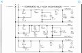
The two 10 watt power resistors on the midrange for my house speakers extremely hot and shutting off the amplifier. What can I do to correct this problem with out changing the frequency response? If you need anymore information I can supply it for you.
 

Attachments

drc_567

Joined Dec 29, 2008
1,156
... a possibility is that one of the series capacitors has failed.
... There are two parallel capacitors in series with the 4 ohm resistors ... Looks like they are labeled C7 and C8. It might be worthwhile to desolder the larger capacitor ... 10uF? ... and check it's value to see if it has shorted out ... maybe the smaller one also.
.... at certain frequencies, the capacitors are supposed to act as impedances. Maybe one of them has worn out. How much use have the speakers seen?
 

Thread Starter

david5559

Joined Jun 16, 2017
10
... a possibility is that one of the series capacitors has failed.
... There are two parallel capacitors in series with the 4 ohm resistors ... Looks like they are labeled C7 and C8. It might be worthwhile to desolder the larger capacitor ... 10uF? ... and check it's value to see if it has shorted out ... maybe the smaller one also.
.... at certain frequencies, the capacitors are supposed to act as impedances. Maybe one of them has worn out. How much use have the speakers seen?
The capacitor C7 -19uF and C8 - .1uF have been replaced and the two 10 watt resistors will burn your fingers if you touch them. The amplifier does not get hot when there is no music playing. They are old but have had minimal use. What can I do with this heating problem because the midrange frequency keeps burning out? The midrange speaker is very clear and crisp until the croosover burns out.
 

Thread Starter

david5559

Joined Jun 16, 2017
10
Sounds like you need bigger resistors, or put the very hot resistors on a heatsink, or turn down the volume.
Is putting bigger resistors going to change the frequency response of the speakers? I am only driving the speaker at 1/3 volume which is nowhere near their capacity. Does anybody out there know how to put in the right components so it will work correctly. I need HELP !!!
 

dendad

Joined Feb 20, 2016
4,637
It sounds to me that you are driving low powered speakers from a high power amplifier.
A good rule is to have your speaker RMS power rating (not "advertising brochure" power) higher that the RMS power of the amplifier.
Running a high power amp into low power speakers is not wise at all. Smoke results!
As noted above, you have not given any power info so your questions are almost meaningless.
 

GopherT

Joined Nov 23, 2012
8,009
Is putting bigger resistors going to change the frequency response of the speakers? I am only driving the speaker at 1/3 volume which is nowhere near their capacity. Does anybody out there know how to put in the right components so it will work correctly. I need HELP !!!

When we say "bigger" resistors in this context, it means the same ohm resistance, just higher power rating. Now, they are going to dissipate the same amount of heat but it will be spread across a bigger area.

Also, describe "hot". This ceramic bar (sand bar) resistors can withstand temps much hotter than your finger. Unless you smell plastic melting, I would say the resistors are ok.
 

Thread Starter

david5559

Joined Jun 16, 2017
10
When we say "bigger" resistors in this context, it means the same ohm resistance, just higher power rating. Now, they are going to dissipate the same amount of heat but it will be spread across a bigger area.

Also, describe "hot". This ceramic bar (sand bar) resistors can withstand temps much hotter than your finger. Unless you smell plastic melting, I would say the resistors are ok.
I will be posting all the information on the speakers and the amplifier tomorrow or the next day. Thank you for all the information I have received so far.
 

#12

Joined Nov 30, 2010
18,224
resistors can withstand temps much hotter than your finger.
I went poking around in an online resistor store and found that some of them are rated for 250 degrees CENTIGRADE.
That's 482 F. Way hotter than your fingers would enjoy! According to this chart. there are only 2 solders that DON'T melt at 250 C.

Code:
Solder Alloy              Melting Point (°C)        Melting Point (°F)
5Sn-95Pb                          307                       585
0.5Sn-92.5Pb-2.5Ag                280                       536
Sn/5Sb                            243                       469
100Sn3                            232                       450
99.3Sn-0.7Cu                      227                       440
96.5Sn-3.5Ag                      221                       430
Sn/3.0Ag/0.5Cu                    219                       426
Sn/3.8Ag/1.0Cu                    217                       423
Sn/3.5Ag/1.0Cu/3Bi                213                       415
50In-50Pb                         209                       402
45Sn-55Pb                         204                       400
55Sn-45Pb                         193                       379
60Sn-40Pb                         186                       368
63Sn-37Pb                         183                       361
62Sn-36Pb-2Ag                     179                       354
97In-3Ag                          143                       289
Sn/57Bi                           139                       282
52In-48Sn                         118                       244
http://www.rfcafe.com/references/electrical/solder.htm
 
Last edited by a moderator:

dendad

Joined Feb 20, 2016
4,637
Just out of interest #12, that feature has been used in equipment. I have seen a power resistor soldered to the underside of a tag strip, the wires not twisted around the tags, just straight across, and it was used as a protection device, like a fuse. If excess current was drawn, the resistor would overheat and melt the solder so it would drop off the tags.
 

#12

Joined Nov 30, 2010
18,224
165W @ 8 ohms
That's 4.54 amps RMS per channel.
(2) 4 ohm in parallel makes 2 ohms
In series with the midrange speaker.
If the midrange speaker carries half the wattage, that's 3.2 watts dissipated by 20 watts worth of resistors.
If all the power went to the midrange speaker and the owner played it maxed out continuously, that would be 41.25 watts into 20 watts worth of resistors.
Considering average power content in music and a bass speaker taking half the power, the math doesn't demonstrate how those resistors can get too hot to survive.

This is, "not a problem" unless something else is broken.
Does the stereo sound right? If so, this is an imaginary problem.
If not, something else is wrong.
 

GopherT

Joined Nov 23, 2012
8,009
I went poking around in an online resistor store and found that some of them are rated for 250 degrees CENTIGRADE.
That's 482 F. Way hotter than your fingers would enjoy! According to this chart. there are only 2 solders that DON'T melt at 250 C.

Code:
Solder Alloy              Melting Point (°C)        Melting Point (°F)
5Sn-95Pb                          307                       585
0.5Sn-92.5Pb-2.5Ag                280                       536
Sn/5Sb                            243                       469
100Sn3                            232                       450
99.3Sn-0.7Cu                      227                       440
96.5Sn-3.5Ag                      221                       430
Sn/3.0Ag/0.5Cu                    219                       426
Sn/3.8Ag/1.0Cu                    217                       423
Sn/3.5Ag/1.0Cu/3Bi                213                       415
50In-50Pb                         209                       402
45Sn-55Pb                         204                       400
55Sn-45Pb                         193                       379
60Sn-40Pb                         186                       368
63Sn-37Pb                         183                       361
62Sn-36Pb-2Ag                     179                       354
97In-3Ag                          143                       289
Sn/57Bi                           139                       282
52In-48Sn                         118                       244
http://www.rfcafe.com/references/electrical/solder.htm
When I've seen them in really concerning situations, the resistor is mounted high off of the board, and hopefully the temp doesn't get maintained all the way down those long leads to the solder joint.
 

#12

Joined Nov 30, 2010
18,224
hopefully the temp doesn't get maintained all the way down those long leads to the solder joint.
That's one of the major reasons to hang 'em high. Those long legs have a resistance to heat flow, and besides that, they radiate.
I have read that you wouldn't want a solid silver spoon to stir your coffee because heat travels through silver so fast it would hurt your fingers.
Obviously, other metals have a lot less thermal conductivity, and restricting the diameter of the path enhances that effect.

Another reason to hang 'em high is so the resistor can radiate on 4 sides instead of 3, with better convection than being blocked on one side.
Why? Because resistors can be built to survive temperatures that would brown a circuit board and degrade the quality of the solder joints.
Anybody who has been in this business for a couple of years has seen that phenomenon.

Here's a chart. Look who's on top for thermal conductivity...silver.
http://www.tibtech.com/conductivity.php
 

tcmtech

Joined Nov 4, 2013
2,867
I for one have never liked that crossover design. I know it's theoretical intent but it's very power wasteful for what little purpose it serves.

Over the years I've redesigned a number of those types of circuits to simplify them and reduce their power losses by taking out the resistors that ran parallel to the speaker circuit. The speaker units never showed any real change in performance other that being a bit louder in the mids and highs for the given power put into them.
 
Top