 Facebook
 Google
 GitHub
 Linkedin
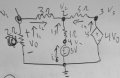
The attached image has the circuit being analyzed.
Using Node Analysis I get:
V1=V0=1.111V , V2 = 2.778V, V3=4V0=4,444V and V4=3V.
I have double checked this in Tina Pro Version 9,3,50.248
Although, performing Mesh analysis, I get a complete different result.
V0 = 2I1
M1: 2I1 + 3I1 + I1 - I2 + 3 = 0 => 6I1 - I2 = -3
M2: -3 + I2 - I1 + 5I2 + 4(2I1) = 0 => 7I1 + 6I2 = 3
Solving this, I get I1 = -0.349A and I2 = 0.907A, what gives me V0 = -0.698V , what is different from Node Analysis result and Tina Pro simulator.
What is wrong here ?
Attachments
-
 30.8 KB Views: 82


") . My main question was about my Mesh analysis. Jony130 answered it properly. I was making confusion with the V0=-2I1, I couldnt understand why it should be negative, after his explanation I could understand it.
. My main question was about my Mesh analysis. Jony130 answered it properly. I was making confusion with the V0=-2I1, I couldnt understand why it should be negative, after his explanation I could understand it.


