Merge common grounds of bridge rectifiers on two different boards

Thread Starter

george66661

Joined May 3, 2018
8
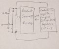
I have 2 boards ----- one has constant current driving circuit and another has conductorless regulator I'd like to power microcontroller to control
constant current driving circuit. Is it ok to connect both common grounds ( dashed line ) to merge
the boards? Is there any issue for capacitors in AC side of 2nd board and 004.JPG DC side of 1st board if both common grounds connected?
Thanks in advance.
 

Colin55

Joined Aug 27, 2015
519
The PIC will only take 20mA -100mA, no matter how much you throw at it.

Just put both on the output of the first circuit.

You can't put a PIC on cc.
 

Thread Starter

george66661

Joined May 3, 2018
8
The PIC will only take 20mA -100mA, no matter how much you throw at it.

Just put both on the output of the first circuit.

You can't put a PIC on cc.
The PIC will only take 20mA -100mA, no matter how much you throw at it.

Just put both on the output of the first circuit.

You can't put a PIC on cc.
Thanks for the advise. I am new in power design. Please refer to the attachment. Is this the configuration you suggest?
BTW;I forgot to mention the constant current driver is for driving 20 series LED ( nominal voltage around 60v @150mA ).
 

Attachments

Colin55

Joined Aug 27, 2015
519
I am really working in the dark as you do not mention the input voltage.
But how do you think you are going to convert 15mA into 150mA? I can do it because I am a magician and I can perform the Indian rope trick and make a monkey climb the 15 metre rope.
 

Thread Starter

george66661

Joined May 3, 2018
8
I am really working in the dark as you do not mention the input voltage.
But how do you think you are going to convert 15mA into 150mA? I can do it because I am a magician and I can perform the Indian rope trick and make a monkey climb the 15 metre rope.
Sorry about the confusion. I describe it more clearly below:
The AC is 120V/60Hz.
150mA constant current driver is connected to 20 series connected LEDs as I mentioned ( so the nominal forward voltage is around 60V )
Since I have no idea to extract the stable 5V from 1st board to power PIC, so I am thinking using conductorless capacitor-coupled switched shunt regulator to do it.

I have 1st board available. I just purchased necessary components for 2nd board. Could you give me the advise the appropriate way to
do it. Thanks.
 

Thread Starter

george66661

Joined May 3, 2018
8
You can buy a 5v module for $5.00
You can buy 60v CC module for $10.00

Just stick them together and it done.
It can't be done that way because the 1st board can't be changed and the rectifiers is on board.
This is why I try to introduce 2nd board which has another bridge rectifiers and CCSS to convert AC to 5V to power PIC which can be used to
control 1st board. The question back to Is it ok to tie both bridge rectifiers commons together? Does it meet my need to provide stable 5V to
power PIC to control 1st board?
 

dendad

Joined Feb 20, 2016
4,476
You will be a lot safer to use an isolated 120V to 5V power supply/plug pack for the PIC.
And an isolated supply for the LEDs too is the way to go.

Hooking stuff directly to the mains is not a good idea if you do not know for sure what you are doing. Smoke and/or death can result.
In fact, I think your questions are running pretty close to "forbidden" subjects on this forum. Potentially very dangerous.

Convert it all to a 24VDC or 12VDC system and use a good power supply so you keep safe.
 

Colin55

Joined Aug 27, 2015
519
I have stopped answering him because he doesn't know what to do. Has no idea of electronics. His idea will not work. His idea is dangerous and he will be cooked like a little sausage on an electric grill.
 

Thread Starter

george66661

Joined May 3, 2018
8
You will be a lot safer to use an isolated 120V to 5V power supply/plug pack for the PIC.
And an isolated supply for the LEDs too is the way to go.

Hooking stuff directly to the mains is not a good idea if you do not know for sure what you are doing. Smoke and/or death can result.
In fact, I think your questions are running pretty close to "forbidden" subjects on this forum. Potentially very dangerous.

Convert it all to a 24VDC or 12VDC system and use a good power supply so you keep safe.
Thanks. Because the constant current board can't be changed and it is non-isolated. This is why I
am thinking tie the commons of two boards.
Just afraid of burning so I ask the question here 1st. I'll just add high voltage DC/DC regulator after bridge rectifiers. My 1st thought is this configuration. I just afraid the voltage fluctuation is going to ruin the stability of 5VDC. Thanks for your advise.
 
Top