Mercury Thermostat

Thread Starter

biferi

Joined Apr 14, 2017
521
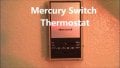
I uploaded an Image of an Old Mercury Thermostat.

I wanted to know one thing about these Old Mercury Thermostats?

Right below the Temperature Numbers is skinny window going from Right to Left.

Is this where people would see what they set it on?

Because all the way on to In betweenwhere it says On and Fan is another window going from Left to Right.
 

Attachments

Thread Starter

biferi

Joined Apr 14, 2017
521
I do know how they did work.

How do you Read the window in the Front?

The skinny window under the Number in Front tells you what you set it to am I Right?
 

sagor

Joined Mar 10, 2019
1,049
I suspect that the top window shows the actual current temperature (thermometer) while the bottom window shows the current setting (by the lever) of the desired temperature.
 

nsaspook

Joined Aug 27, 2009
16,275
I do know how they did work.

How do you Read the window in the Front?

The skinny window under the Number in Front tells you what you set it to am I Right?
It depends on the model. Some only had a setpoint indicator or temp read back. Other types had both.

That's why I posted the video.
 

Thread Starter

biferi

Joined Apr 14, 2017
521
If I am connecting this type of thermostat I know I will use just the Top Screws for a Conventional System that uses 1. Power Transformer.

So I know I put the Red Wire to the Screw that says R.

Then the Screw that says R will have a Jumper going from it to the Screw that says RC.

If I have a 2. Power Transformer System I will remove the Jumper going from the Screw that says R going to the Screw that says RC.

I know I still would put the Red Wire to the Screw that says R but what Wire would I put to Screw that says RC?
 

MisterBill2

Joined Jan 23, 2018
27,368
OK, I can explain that R and "RC" two 24 volt feed connections: First, "R" for red is the 24 volts feed for the heating system, which originally the heating contact was to the white wire, to operate the gas valve or the hot water circulation pump in a hot water heating system. For forced air heating systems the blower is usually switched on by a thermostat inside the furnace when the heat exchanger is hot enough to provide warm air delivery.
For the common gas fired furnace that also has a cooling system that uses the same fan and duct-work to deliver cooled air, many, but not all of them, used the same 24 volts transformer to operate the contactor (power relay) to activate the condenser system AND to operate another relay in the furnace package that switches on the blower, to circulate the cooled air. That requires the blower to switch on immediately, because the cooling in the evaporator starts rapidly when the compressor is running. Many systems use the same transformer for both functions.
BUT the "RC" terminal is for those systems that have a separate transformer, often built into the condenser package, to power the compressor power contactor. For those systems the feed for the cooling system needs to be separated to avoid the thermostat connecting the two transformers in parallel, which could produce an effective shorted circuit problem. THAT is the reason for the RC terminal on the thermostat.
 

Thread Starter

biferi

Joined Apr 14, 2017
521
So if I understand you a System that has another Power Transformer for the Compressor will use the Screw that says RC.

You still would use the Screw that says R as well Right?
 

Thread Starter

biferi

Joined Apr 14, 2017
521
I think I get it now.

If I have a 2. Power Transformer System I would take the Jumper going from Screw R to Screw RC.


Then I would just put my Red Wire to Screw RC.

Do I have this Right?
 

MisterBill2

Joined Jan 23, 2018
27,368
The second red wire from the cooling system will connect to the RC terminal, so yes.
There are also ways to revise the scheme to not use the second transformer. They are confusing and subject to misunderstanding, so I did not try to explain that scheme.
 

Thread Starter

biferi

Joined Apr 14, 2017
521
Now I think I understand.

If I have a 1. Power Transformer System I will just have one Red Wire.

If I have a 2. Power Transformer System I will have two Red Wires.

So if I had a 2. Power Transformer System how do I know witch Red Wire is 1. and 2. or do I not get this yet?
 

MisterBill2

Joined Jan 23, 2018
27,368
Now I think I understand.

If I have a 1. Power Transformer System I will just have one Red Wire.

If I have a 2. Power Transformer System I will have two Red Wires.

So if I had a 2. Power Transformer System how do I know witch Red Wire is 1. and 2. or do I not get this yet?
NOW you are asking a harder question. In most cases the systems in a separate transformers system, if they are isolated, will only show a voltage between the single pair for the heating system. Cooling systems also will have the voltage between both the compressor control line and the fan/blower control line. So yo will need a way to test for the AC voltage between the wires. Most residential heating/cooling systems use 24 volts AC for control, and almost any meter able to include that voltage on some range will be good enough.
 
Top