Hm.. And to make sure i understood, so lets i have to measure the voltage for every componen in the same direction? pretty much same as the KVL equation. What i mean by that is if i measured the Vc and Vb, from the top to the bottom, assuming the Base and Collector is top, and ground is bottom, so i have to measure the Vcb in the same way? Collector from the circuit looks higher than base so measuring from the top to bottom would give us -0,5V
Hmm. i will add a circuit. So if we connected the negative battery side to the Emmiter , and we have collector (cathode) from which we are measuring the voltage, so the both sides are negative? Am i wrong?
Hmm. i will add a circuit. So if we connected the negative battery side to the Emmiter , and we have collector (cathode) from which we are measuring the voltage, so the both sides are negative? Am i wrong?
Both sides negative with respect to what ? To measure the voltage we need at least two point in the space. One of this point is treat as a reference point. We have a very similarity situation when we try to measure a height of an object. We need a reference point. The most common reference pint is "above mean sea level". But when you measure the height of the table in your house the floor now becomes your reference point.
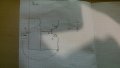
As an exercise try to find the voltage between the various points in this circuits.
From what I see this "diode model" do more harm than a good. So try to forget about all this diodes.
And of course your diagram is wrong.
In NPN transistor the most "useful" mode of operation is called "active-region/forward-active" or even a linear mode.
And the NPN will "enter" this mode if:
- Base-Emitter junction is forward biased (usually at VBE > 0.5V)
- Base- junction is reverse biased (VBC < 0V or VCB > 0V)
Additional in this mode transistor has a amplifier ability. But transistor is not a source of a energy.
What transistor do in the circuit? Transistor can only "control" the flow of a energy from the source (power supply) to the load. In exactly the same way as a water tap can "control" the flow of a water.
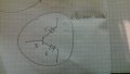
This image show how BJT "amplifier the current".
Also don't forget that amplifier is a device that allow as control the flow of "high power" by helps of a low power. To the Amplifier effect occurred, two things are necessary: source of energy (power supply) and a device for controlling the flow of this energy - > the amplifier.
And yes, the conventional current will from from Collector to Emitter.
Okay. So we lets say if we measure the voltage Vbc so the first letter (b) means that we are gonna imagine multimeter positive lead at B and negative at C?
Well thats a shame but doesnt seem like i would know how to correctly measure those voltages across points...
maybe if we take picture b)
Vac = +21
Vbd = -21
Vad =+3
Vbc = -3
am i right?
Okay. So we lets say if we measure the voltage Vbc so the first letter (b) means that we are gonna imagine multimeter positive lead at B and negative at C?
Unfortunately not.
Please notice that Va is 12V greater than Vb and, hence Vab = 12V and Vba =- 12V. Also notice that Vb and Vd are connected together to our reference point (ground). This means that by convenient we declare that Vb and Vd is at 0V.
If above is true we have this:
Vac = Va (with respect to ground) - Vc (with respect to ground) = 12V - 9V = 3V.
What do you exactly mean, by connecting Vb and Vd to the ground? how it can become 0V from -12V and - 9v
Hm.. Yeah seems clear that Vac should be 3V, not +21V, but i understand it in the other way.. If we place the positive multimeter lead to the positive battery terminal, we get positive voltage ( in this caes +12V) , and if we take other multimeter lead ( the black one ) and measure also the positive voltage on Vc, we are gonna get negative voltage, so -9V, so Vac we get +12-9=+3V?
We need two point in the space to be able to measure the voltage. And the idea of a voltage at a single point is meaningless.
You cannot say that voltage at point D is -9V without telling us the location of a second point.
So all we can say is that the voltage at point D is minus 9 volts lower than the electric potential at point C.
Also notice that by doing this (measurement) we automatically "set" point C as a our reference point and declare that VC = 0V.
In picture b both Vb and Vd are "attached" to our reference point. And by doing this we declare that Vb and Vd are at 0V.
What this means in practice? We simply connect Vb and Vd together via a thick wire. Additional we connected the black probe to this ground also.
And we do all our measurement with this black probe connected to ground. We never remove it from there.
Hm. So what i have understood from that is basicaly when we measure voltage between 2 points, the second letter is our reference point? For example Vcb, means that we are measuring voltage at Vc to our reference point Vb. Is it correct to say backwards? I mean if i say Vcb, the reference point B wouldnt be correct? .
Hm. I still ant figure it out. If we measure the Vba. so the second letter (a), means that our reference point, where we will be putting multimeter black lead will be A, and B will be the positive?. We are measuring the voltage backwards as we put the r so we should get -12v. All in all, what i have wanted to make sure, is that reference points depends on how u write the letters?
Vab - reference point (ground) is B, so we measure the voltage between A (positive lead) ,and B-negative multimeter lead..
Vbc - reference point is C
So the reference point(ground)is always second letter, and the multimeter black lead always should go to ground?
Also, can you tell me if the way i think is correct in the previous message? Hm.. Yeah seems clear that Vac should be 3V, not +21V, but i understand it in the other way.. If we place the positive multimeter lead to the positive battery terminal, we get positive voltage ( in this caes +12V) , and if we take other multimeter lead ( the black one ) and measure also the positive voltage on Vc, we are gonna get negative voltage, so -9V, so Vac we get +12-9=+3V?
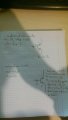
I also thought about transistor, by the way, about the transistors, why assuming junctions as diodes is not the best idea to get fammiliar with they working principle? adding a photo
I also thought about transistor, by the way, about the transistors, why assuming junctions as diodes is not the best idea to get fammiliar with they working principle?
That method can be useful if NPN or PNP doesn't make sense to you. But for it to be useful, you have to draw the correct number of diodes and draw them in the correct orientation.
Both of your pictures are wrong. In the top one, you have the CB diode drawn backwards. In both you have an extra diode on the base.
The diodes are formed by the PN junctions in the transistor. A transistor only has 2 junctions, therefore 2 diodes.
I dont get why im wrong with the.top one. If the CB junctions is reverse biased, that means the.collector is positively charged and base is negatively charged... And assuming that current flows from + to - we get current flow from collector to base
Yeah, but if i remove a diode on the bass, im left with 2 junctions, so now its okayy? How can CB current be backwards and floe from -(base) to + (collector)
 Facebook
 Google
 GitHub
 Linkedin