Measuring I with oscope in a HV circuit?

Thread Starter

electronice123

Joined Oct 10, 2008
350
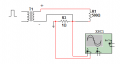
I want to use my scope to measure current in a series circuit, the only problem is the circuit operates at higher voltage than the scope can handle.

I was thinking of soldering (3) 1Ω resistors together and placing them in series in the circuit.

Each resistor will have 20mV max across it (Ipk is less than 20mA). My thinking is that I will measure only across the center resistor, that way I have 20mV on either side instead of -500V or +500V.

Is this an effective way to measure current in my circuit and protect the scope from the HV?
 

ericgibbs

Joined Jan 29, 2010
21,439
hi,
You will still have HV present on the 3, 1R resistors relative to common/ground.

Post a diagram showing the resistors etc.
E
 

to3metalcan

Joined Jul 20, 2014
263
I think the OP is planning to connect his probe to one end of the resistor and his scope's ground to the other. You actually don't even need three resistors...one in series with the rest of the circuit would be fine. I do this to check bias on vacuum tubes in amplifiers, with B+ voltages above 500V, which would nuke my meter. The resistor has to go in series between the circuit and ground...this is the ONLY safe place to put it.
 
Last edited:

alfacliff

Joined Dec 13, 2013
2,458
there are clamp on probes for scopes to measure current. I use one from tektronix at work. not the kind you use to measure the current in a 60 hz circuit, these are made for higher and lower frequencies. check on some of the test equipment sites.
 

Lestraveled

Joined May 19, 2014
1,946
What kind of bandwidth do you need?

There are also hall effect current sensors. These are great devices in that they measure down to DC with complete isolation.
 

Thread Starter

electronice123

Joined Oct 10, 2008
350
Yes I thought I could just place the three resistors in series with the rest of the circuit, then place the probe leads across the center resistor. Frequency is 5kHz.

Buying a current probe is out of the question for me as they are way to expensive.
 

MrChips

Joined Oct 2, 2009
34,807
You cannot simply connect the probe leads of a grounded scope across any resistor.
You have a few options:

1) Put the current sense resistor on the ground side of the circuit.
2) Use a floating or battery operated scope such as a Fluke Scopemeter.
3) Power the scope from an isolation transformer.
 

MrChips

Joined Oct 2, 2009
34,807
Why do you need three resistors when one will do?
There is no protection provided by the extra two resistors.
You need to connect the resistor to GROUND.
 

ericgibbs

Joined Jan 29, 2010
21,439
hi,
Your circuit looks OK.
Ensure that the 1R wattage rating can carry the load current, also many low value resistors are not tight tolerance resistors.
E
 
Top