Measuring current

Thread Starter

KansaiRobot

Joined Jan 15, 2010
324
Hello everybody and thanks for your help.

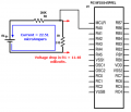
I have connected the following circuit.
schemeit-project.png

and now I want to measure the current going in several places. (for example RA0, RC0, RB5, RB4, etc)
The thing is I cant do it :(

Please dont tell me to search in the internet. I have. For example:
https://learn.digilentinc.com/Documents/135
so I know the theory. (I have measure current in the past I remember too)

But somehow, for example I cant measure the current so can someone teach me where should I put the connections of my multimeter?? I am using the fluke multimeter.

I for example broke the circuit going to RA0 and put the multimeter there... and nothing... 0 Amp always.
I measure the voltage, it is working fine. but always 0 Amp. and I am sure that is not true,

I cant either analyze that circuit to theoretically calculate the current. I mean maybe the one with the switch that seems simple (like in all textbooks, why textbooks only have simple examples)

Other than that my motor doesnt move with the 0.1μF capacitor, I had to take it out.

I would like to measure the current in the motor as well, but I cant even do something simple as the one in the potentiometer.

Help very much appreciated

EDIT: I have tried the simplest of circuits (in that homepage) My multimeter doesnt even measure that. Am I doing something wrong with the connections I wonder... I put the red cable in A and the black cable in COM and put the lever in A

EDIT2: I found that probably the fuses got blowed.... :(
How can I repair that....

And if someone can teach me to calculate currents theoretically in this circuit I would be very much grateful.
 
Last edited:

Thread Starter

KansaiRobot

Joined Jan 15, 2010
324
I am very sorry if my question seem stupid or petulant but really I am totally confused (and as I said even the simplest circuit analysis confuse me.. it is not like programming or something).
So please allow me. I implemented the following

schemeit-project.png
very simple circuit. I think my multimeter fuses are blown so what I did was measure the voltage drop between both ends of the R1 resistor and it is 11.6mV (later I dont know why it incremented to 30 mV)

using Ohm law I calculate that the current must be I=0.030v/510= 0.05mA
so very small current right??

Then why is my battery pack so hot and some smell of burn is starting to come to my nose...? :oops:

any help? please

EDIT:
I run an analyzer in this circuit and the current must be 22.7μA
so that is very low current right?
I am still puzzled about the smell and hotness
 
Last edited:

MrCarlos

Joined Jan 2, 2010
400
HelloKansaiRobot

It is very likely that the internal fuse on your multimeter is burned. In the user manual describes how to open the multimeter to replace these fuses.

You have carefully studied the data sheets for TA7291P??.
The same as the data sheets for PIC18F2550.

The current flowing in those terminals that you mention is extremely low, you probably can not measured with Your multimeter.

However, the outputs on TA7291P that drive the motor, there You can measure current,

I see that the scheme you enclose, there is a potentiometer connected to RA0 port of PIC.
With this Pot are you adjusting the speed of the motor??

Check the internal fuses of Your multimeter. On the back, usually, have screws that must be removed to open and test the fuses.

You verified that the TA7291P be able to move the motor You have in your physical design??

You can download data sheets from here:
http://www.alldatasheet.com/
 
Last edited:

Thread Starter

KansaiRobot

Joined Jan 15, 2010
324
Thank you for your reply. I will read it carefully and reply later.

In the meantime a rather **simple** question that I hope someone answer me.

Let's say I have a circuit. >>any circuit<< and I have already analyzed the voltage and current in it.
What happens if I connect one part of this circuit to a pin of a IC?? How much is the current entering the pin, and how can I measure with a multimeter?

For example in
schemeit-project1.png

how much current is entering the PIC??
---
I ask this because in the examples there is usually only simple circuits, that all end in ground, But a cable entering a pin of an IC has no ground, or at least not immediate.
 
Last edited:

Alec_t

Joined Sep 17, 2013
14,280
The internal resistance presented by an input pin of an IC such as a PIC is generally very high. The datasheet should indicate the current that it draws. It may typically be only one or two microamps, which an inexpensive meter probably won't be able to measure. The IC has a ground connection through which currents flow.
 

wmodavis

Joined Oct 23, 2010
739
Sounds like the fuse in the DMM is open not letting you measure current. Check that first! That can happen if you leave the DMM set to measure current and you attempt to measure a voltage. That voltage can cause a high current to flow through the fused ammeter circuit and pop the internal fuse. The DMM will then no longer be able to measure current.
 

crutschow

Joined Mar 14, 2008
34,285
Currents in a circuit are generally difficult to measure. That's one big advantage of a Spice simulator -- you can easily display the currents anywhere in the circuit.

If you have a resistor in the real circuit, then you can measure the voltage across the resistance and then calculate the current using Ohm's law.
 

MrCarlos

Joined Jan 2, 2010
400
Hello KansaiRobot

Let's analyze the circuit that you enclose in your post #4.

The current flowing in the circuit formed by the battery, R2 and R1 is: 6 / (R2 + R1) = I. So I = 0.00002251 Amp. = 22.51 microampers.
This current flows through R1 so the voltage drop across its terminals would be V = I x R = 0.0114801 V. = 11.48 miliVolts.

BUT CURRENT WILL NO FLOWS into the PIC port RA0 because there is a open circuit between the PIC ground and Your external circuit. (Battery, R1 and R2)
So Your Question: how much current is entering the PIC??. . . The answer is: NO CURRENT FLOW(entering) To the PIC.

Notice:. . . If applying 5 Volts to RA0 circulate, something like, 2.5 microampers, applying 11.48 miliVolts How much current you think that circulate ??.
Assuming you have connected the negative pole of the battery with the PIC Ground.

Oh boy, I just read your post #2. (You've edited).
Circuit simulators is another story. They already bring the connections by default bias for IC's


.
 

Attachments

Last edited:

DickCappels

Joined Aug 21, 2008
10,152
The post by MrCarlos is missing some spaces for some reason. wmodavis also made the same point. I would check out their concern before spending time looking at other solutions. Corrected, MrCarlos's post reads (emphasis mine):
HelloKansaiRobot

It is very likely that the internal fuse on your multimeter is burned. In the user manual describes how to open the multimeter to replace these fuses. <some text removed for brevity>
 

MrCarlos

Joined Jan 2, 2010
400
Hello DickCappels

Yes indeed missing some spaces in my message #3. Something strange is happening with my LapTop. I edited my post and I corrected.
Sorry for the inconvenience.

About my post #8.
I just try to answer the question of KansaiRobot in post #4: how much current is entering the PIC ??
 

Thread Starter

KansaiRobot

Joined Jan 15, 2010
324
Hello KansaiRobot

Let's analyze the circuit that you enclose in your post #4.

The current flowing in the circuit formed by the battery, R2 and R1 is: 6 / (R2 + R1) = I. So I = 0.00002251 Amp. = 22.51 microampers.
This current flows through R1 so the voltage drop across its terminals would be V = I x R = 0.0114801 V. = 11.48 miliVolts.

BUT CURRENT WILL NO FLOWS into the PIC port RA0 because there is a open circuit between the PIC ground and Your external circuit. (Battery, R1 and R2)
So Your Question: how much current is entering the PIC??. . . The answer is: NO CURRENT FLOW(entering) To the PIC.

Notice:. . . If applying 5 Volts to RA0 circulate, something like, 2.5 microampers, applying 11.48 miliVolts How much current you think that circulate ??.
Assuming you have connected the negative pole of the battery with the PIC Ground.

Oh boy, I just read your post #2. (You've edited).
Circuit simulators is another story. They already bring the connections by default bias for IC's


.
Thank you MrCarlos for your post. Answering your question if 5 V generate 2.5 microampers, 11.48miliVolts would create 0.00574 microamperes, I think...
So the current applied to a IC depends on the voltage applied? In other words the IC acts like a giant resistor???
(and yes the IC has its ground pin connected to ground)
 

MrCarlos

Joined Jan 2, 2010
400
Hello KansaiRobot

Why you fall into these conclusions: So the current Applied to a IC depends on the voltage Applied?. In other words the IC acts like a giant resistor ???

Remember that internally the PIC has not only resistance. Has different types of components; such as:
Transistors of various types.
Diodes, of various types.
Which do not have a linear response.
And of course they have:
Resistors, Capacitors, Etc.

So it's not as simple as: 2.5 mAmp. / 5V. x 11.5 mV. = 0.00574 mAmp.

Let's assume, for a moment, that the PIC input RA0 only has a resistor connected to the base of an NPN transistor. Emitter to ground and its collector resistor to VCC.
Let's assume, too, that by applying 5V to RA0, a current of 2.5 mAmp flow.
If, now, you apply at the same input 11.5 mV. (Rather than 5V) the current will not be 0.00574 mAmp.
Because the base-emitter junction of the transistor does not respond linearly.

But Yes indeed, the current applied to an IC depends on the applied voltage.
Unfortunately we do not know what's in that input RA0 of PIC.
 
Top