Measuring blank transformer, a bit lost

Thread Starter

watchmania

Joined Jan 30, 2018
11
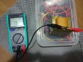
So long story short, I bought a cheap yet nice-sounding local keyboard amp. However, after 20-30 hours of usage, it stopped working, completely dead.

I took it apart and found that the primary transformer winding breaks (open circuit). Given that the transformer is blank, with no marking whatsoever, looks like the easiest replacement would came from the manufacturer. So the manufacturer sends me out a new transformer for the amplifier for free.

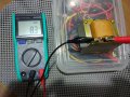
Worry of having the same issue in the future, I decided to measure the new transformer so I can get a replacement myself if it breaks again.

However, I'm stuck on the D-E-F outputs measurements. The resistance on D-F and E-F shows zero?? Yet the voltage seems weird too. Would be glad if someone can enlighten me.

primer.jpg sekunder.jpg measure.jpg

Voltage (AC)
2 - 3 = 24.41 V
3 - 4 = 24.39 V
1 - 3 = 28.89 V
3 - 5 = 28.55 V
2 - 4 = 48.62 V
1 - 5 = 57.27 V

6 - 7 = 16.29 V
7 - 8 = 16.33 V
6 - 8 = 32.51 V

D - E = 11.86 V
E - F = 13.25 V
D - F = 12.71 V

Resistance:
A - C = 135.1 ohm
A - B = 123.3 ohm
B - C = 11.9 ohm

1 - 3 = 3.5 ohm
3 - 5 = 3.5 ohm
1 - 5 = 7.1 ohm

6 - 8 = 23 ohm
6 - 7 = 12.3 ohm

D - E = 8.3 ohm
E - F = 0 (???)
D - F = 0 (???)

Thank you in advance!
 

Thread Starter

watchmania

Joined Jan 30, 2018
11
How did you measure zero resistance?
Hi crutschow, attached the pictures I took while measuring resistance between the D-E-F. Btw I think it's not zero resistance, just open circuit.

Is there any other thing I can measure? I mean before I install the new transformer to the amp?
 

Attachments

dendad

Joined Feb 20, 2016
4,451
Try to get a service manual or at lest a circuit from the manufacturer. That will help.

I think it's not zero resistance, just open circuit.
And your comment above is not unique. Quite a few times people equate not reading a resistance (open circuit) with "zero resistance". Actually it is the opposite. And you can imagine how it does confuse us as we try to help ;)
 

Thread Starter

watchmania

Joined Jan 30, 2018
11
Try to get a service manual or at lest a circuit from the manufacturer. That will help.
In this country, for a local products like these.. service manuals are impossible :p
Actually the technician suggests me just to send over the amp unit so they can fix it. But seems like too much work for this budget amp. Plus if I can reverse engineering the transformer, I can find a better quality ones myself -- not to mention learning something new ;)

And your comment above is not unique. Quite a few times people equate not reading a resistance (open circuit) with "zero resistance". Actually it is the opposite. And you can imagine how it does confuse us as we try to help ;)
Sorry about that :p. I really wanted to edit the first post but seems like it's not doable here?
 

dendad

Joined Feb 20, 2016
4,451
My guess is something like this...
transformer.jpg

I don't know what your main voltage is so A could be neutral, B = 110V, C = 120V or A could be neutral, B = 220V, C = 240V.
probably the voltage readings you read on F are capacitive loading as the multimeter is high impeadance.
And if D-E do not connect to the mains winding, it could be another winding of 11V.
All readings are a bit approximate with no load.

The power can be calculated by looking at the area of the metal through the center of the windings, along with the mains frequency.

http://www.giangrandi.ch/electronics/trafo/trafo.shtml
 

Thread Starter

watchmania

Joined Jan 30, 2018
11
I don't know what your main voltage is so A could be neutral, B = 110V, C = 120V or A could be neutral, B = 220V, C = 240V.
Thank you very much, well educated guess. Yes we use 220V here so I suppose B=220V and C=240V.

probably the voltage readings you read on F are capacitive loading as the multimeter is high impeadance.
And if D-E do not connect to the mains winding, it could be another winding of 11V.
All readings are a bit approximate with no load.
The miliion dollar question is, is the D-E-F supposed to be single winding hence the (new) transformer is actually.. broken??

As the D-E-F is actually connected to the power amp board as attached.
 

Attachments

dendad

Joined Feb 20, 2016
4,451
Have a look at the amp. Where do the wires go to?
Are you able to trace the circuit at all?
The "F" could be a shield. How does the resistance readings compare to the old transformer?

And check the "D-E" resistance to any other pin.
 

Thread Starter

watchmania

Joined Jan 30, 2018
11
Have a look at the amp. Where do the wires go to?
Are you able to trace the circuit at all?
Wires go like this (completely different from what my buddy's power amp kits are, where they usually just took a set of voltages.. this one seems to use 3 sets!)

wiring.jpg rhoad-power-wiring.jpeg

The "F" could be a shield. How does the resistance readings compare to the old transformer?
Great idea, time to desolder the old transformer. Back soon!

And check the "D-E" resistance to any other pin.
D to any other pins/body except E = open
E to any other pins/body except D = open
 

dendad

Joined Feb 20, 2016
4,451
And have a close look at the D E F tabs to see if D and F have one wire while E has 2 wires. And that there is a good solder joint from wire to tab. It may be the varnish was not cleaned off the wire and F is not connected.
And have you compared the 2 transformers resistance readings?

Does the map do anything at all?

I will have to go soon anyway, so unless someone else comes along, this will have to wait until a later time.
 

Thread Starter

watchmania

Joined Jan 30, 2018
11
And have you compared the 2 transformers resistance readings?

Does the map do anything at all?

I will have to go soon anyway, so unless someone else comes along, this will have to wait until a later time.
Hi Dendad, no worry you can go. No rush here, I'll have some time to continue this stuff like in 2-3 hours anyway.
 

Thread Starter

watchmania

Joined Jan 30, 2018
11
Confirmed. The old transformer (broken primary) measurement on D-E-F are:

Old transformer
============
D - E = 8.3 ohm
E - F = 8.3 ohm
D - F = 16.6 ohm

The new transformer D-E-F is shot.
 

dendad

Joined Feb 20, 2016
4,451
Have you checked to see if the wire ends are attached with a good solder joint to the tags? It may be a dry joint. But it probably would work anyway in a sort of fashion. I would thing the wire is thick enough so as to pretty strong and you may get lucky with a solder fix. Scrape the varnish off the wire first if you need to.
And as the old transformer is crook, have a careful dig to see if there is a thermal fuse in the winding. If so, you may be able to replace it or bridge it out.
With the transformer you have it may net be accessible even if there is one.
I think I'm off to bed soon and not stay up to see the Luna eclipse tonight as it will go over midnight and I'm tired. One of the side effects of getting old ;)
 

Thread Starter

watchmania

Joined Jan 30, 2018
11
Have you checked to see if the wire ends are attached with a good solder joint to the tags? It may be a dry joint. But it probably would work anyway in a sort of fashion.
Solder joints between the wire ends and the tags seems nonexistent, wire ends are just being wrapped there :confused: Tried tightening it but no luck..

And as the old transformer is crook, have a careful dig to see if there is a thermal fuse in the winding. If so, you may be able to replace it or bridge it out.
With the transformer you have it may net be accessible even if there is one.
I think I'm off to bed soon and not stay up to see the Luna eclipse tonight as it will go over midnight and I'm tired. One of the side effects of getting old ;)
I doubt this garbage had any fuse compared to that shiny transformer in the video.

The 12-CT-12 winding is probably some kind of mixer input power, so yeah I guess it would still work without the F tags being connected. Though maybe it will cause some noise?

Anyway, I just got another COTS transformer from my buddy. Looks like the voltage will be close enough, just a bit lower by 1-3V each. See if I have any luck with this supposedly better transformer.

It's ironic that my bachelor degree had lots in common with eclipses, and I can even access a telescope to do so, yet I'm still right here trying to get my amp back to work :)
 
Last edited:

dendad

Joined Feb 20, 2016
4,451
I was having trouble getting to sleep so had a quick look here.
Solder joints between the wire ends and the tags seems nonexistent, wire ends are just being
Have a go at soldering the wires. If the solder does not take, that may be the problem. The insulation on the wires is still there. If so, scrape it off if you can and solder again. That may fix the transformer for you. An easy test.
 

Thread Starter

watchmania

Joined Jan 30, 2018
11
So installed the "better" transformer. LED on check, fan on check, but no sound at all.

IMG_20180131_191811_1517411068797.jpg IMG_20180131_212143.jpg

Guess it will be a question for another day.. o_O
 
Last edited:
Top