 Facebook
 Google
 GitHub
 Linkedin
Hi,
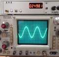
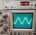
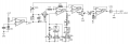
I'm trying to measure an inductor by applying a 4V p-p sinewave across an RL circuit (circuit.png). Increasing the SW frequency until the voltage across R drops to 2V p-p, noting the frequency, I can then calculate the inductance.
What I expect is that at a given frequency, the V p-p across R plus the V p-p across L = V p-p signal generator. This appears not to be the case. Approximately V p-p R + V p-p L = 5V > V p-p siggen. Should it be? Any ideas on what I'm missing here?
Thanks,
hrs
Attachments
-
 19.7 KB Views: 21
 -
 48.4 KB Views: 21
 -
 43.4 KB Views: 18
 -
 44.6 KB Views: 18
 -
 41.3 KB Views: 18

")


