 Facebook
 Google
 GitHub
 Linkedin
I have recently acquired a treadmill for free.
Original fault: Plug into 110V Non-GFCI 20Amp circuit, ON/OFF CB Switch to ON; belt goes to max for ~1sec then power resets and repeats.
Steps taken:
1. Unplug from wall outlet, open motor cover, check all terminals and headers, verified that they are seated correctly. Removed motor connections from control board, removed motor, pulled & cleaned brushes, visually inspected commutator. Reinstalled brushes, reinstalled motor and motor connections to control board. Reinstalled cover, plugged into wall outlet.
2. Power on, Console boots successfully, belt does not spin-up on boot. All buttons work on console, incline motor functions properly. Belt motor fails to spin while speed is set and distance indication increases. Turned off power switch, unplugged from outlet removed motor cover, removed motor dc connections from control board. Plugged in to wall outlet, set power ON, set speed to max on console, connect multi-meter to control board A+ & A- obtained reading of 0.0vdc. Shut down treadmill, unplugged from wall outlet.
3. Removed all control board electrical connectors, removed control board, removed control board from heat-sink tray, discharged C7. Started measuring resistance from DB1 and worked my way to the motor, I got an open circuit indication when I measured across R21.
I have called Icon and asked about a circuit diagram, they directed me to the block diagram included with the treadmill, I made it clear that I needed to get the resistance values. I don't recommend calling Icon/Nordictrack if you need technical answers.


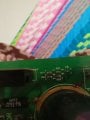
I replaced R21, I thought I read the R21 bands as Green, Brown, Brown, Gold, and I was wrong. R21 smoked when I set a spped and pressed start, and R22 is now cooked and unreadable too. A high res photo of a correct model circuit board would be helpful if there are no circuit diagrams.
I have studied the reverse engineered MC2100 diagram that I found on this site, but I doubt it's accuracy for my specific model.
Original fault: Plug into 110V Non-GFCI 20Amp circuit, ON/OFF CB Switch to ON; belt goes to max for ~1sec then power resets and repeats.
Steps taken:
1. Unplug from wall outlet, open motor cover, check all terminals and headers, verified that they are seated correctly. Removed motor connections from control board, removed motor, pulled & cleaned brushes, visually inspected commutator. Reinstalled brushes, reinstalled motor and motor connections to control board. Reinstalled cover, plugged into wall outlet.
2. Power on, Console boots successfully, belt does not spin-up on boot. All buttons work on console, incline motor functions properly. Belt motor fails to spin while speed is set and distance indication increases. Turned off power switch, unplugged from outlet removed motor cover, removed motor dc connections from control board. Plugged in to wall outlet, set power ON, set speed to max on console, connect multi-meter to control board A+ & A- obtained reading of 0.0vdc. Shut down treadmill, unplugged from wall outlet.
3. Removed all control board electrical connectors, removed control board, removed control board from heat-sink tray, discharged C7. Started measuring resistance from DB1 and worked my way to the motor, I got an open circuit indication when I measured across R21.
I have called Icon and asked about a circuit diagram, they directed me to the block diagram included with the treadmill, I made it clear that I needed to get the resistance values. I don't recommend calling Icon/Nordictrack if you need technical answers.
I replaced R21, I thought I read the R21 bands as Green, Brown, Brown, Gold, and I was wrong. R21 smoked when I set a spped and pressed start, and R22 is now cooked and unreadable too. A high res photo of a correct model circuit board would be helpful if there are no circuit diagrams.
I have studied the reverse engineered MC2100 diagram that I found on this site, but I doubt it's accuracy for my specific model.
Attachments
-
 151.1 KB Views: 769
.jpeg")

") is it a nice commercial model, you workin for the gym, or hombody model? you may get more excercise repairing it than you get using it - maybe.
is it a nice commercial model, you workin for the gym, or hombody model? you may get more excercise repairing it than you get using it - maybe.


