Facebook
 Google
 GitHub
 Linkedin
MaxHeadRoom
- Joined Jul 18, 2013
- 30,732
If this is used off of the TM it is OK to run without HS for a short period for testing.
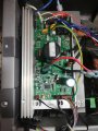
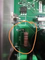
The IRF250 is a Mosfet, to drive the motor, the SCR is next to it and is usually a S4025 etc.
U1 is the PWM opto input to the Micro, U2 send data to the console IIRC it is the belt sensor
The IRF250 is a Mosfet, to drive the motor, the SCR is next to it and is usually a S4025 etc.
U1 is the PWM opto input to the Micro, U2 send data to the console IIRC it is the belt sensor