Ok, I didn´t expose this properly. Lets start again and my apologies for messing with this (and I don´t speak english very well. Excuse me if I make mistakes)
I want to make a small arc generator to find leaks in glass vacuum sealings.
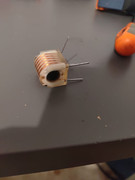
The idea is to use this small transformer with a voltage multiplier, wich I have already tried and works very well, 1cm sparks. I´ll run it for short periords, 3 or 5 seconds really.
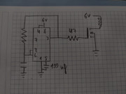
To run the transformer I´m using this NE555 oscillator, the other capacitor is 100nf and the resistor without value is a potentiometer to get 7,4KHz.
The problem is that I have tried some mosfets and they get very hot if I use them without heatsink. The IRFP450 don´t get very hot, but I think it shoudn´t get any hot.
As you can see, I don´t have very much idea about electronics, so any advice or correction will be welcome. I only want my arcs to find the leaks haha.
The old NE555 was invented 53 years ago and was sold beginning 52 years ago.
With a 6V supply, its unloaded output gets as high as only 4.6V.
Most Mosfets need a gate-source voltage of 10V to turn on well but a few "logic level" Mosfets turn on well with only 5V.
Modern 555 ICs are Cmos and have outputs that go as high as the supply voltage. They are ICM7555, LMC555 and TLC555.
But their output current is low and cannot properly drive the high capacitance of the gate of a Mosfet quickly at high frequencies.
Your circuit develops a high voltage spike at the coil and drain pin of the Mosfet when the Mosfet turns off, then a high voltage Mosfet might be needed for it to survive. You want the high voltage spike then a diode cannot be used to cancel the high voltage spike.
So, since I know that the right frequency is 7,3 Khz, I could make an oscillator without the 555 to run the mosfet. The problem is I have no idea how to make it.
Or I could use a NE555 with for example 12volts, to get at least 10 volts to the gate and reduce the current to the coil because I think 12 volts would be too much for this small coil Right?
How could I reduce the current to the coil? A capacitor in series wont work very well because the frequency is too high
Hahaha. I am still learning. The problem is the circuit of the 555 is quite simple and I can understand how it works. You control de frequendy with the charging time of a capacitor, but I can´t find in internet a circuit to use the UC3842 as a variable frequendy oscillator.
Hahaha. I am still learning. The problem is the circuit of the 555 is quite simple and I can understand how it works. You control de frequendy with the charging time of a capacitor, but I can´t find in internet a circuit to use the UC3842 as a variable frequendy oscillator.
Yes, but I have no idea how to connect the rest of the pins. For example in the 555 timer i have to use a 100nf capacitor in PIN REST and CONT and the IC you say doesn´t have these pins. I have looked up and I only see using the IC to more complicated flyback converters and power supplys
Yes, but I have no idea how to connect the rest of the pins. For example in the 555 timer i have to use a 100nf capacitor in PIN REST and CONT and the IC you say doesn´t have these pins. I have looked up and I only see using the IC to more complicated flyback converters and power supplys
You are not using the feedback circuitry, so you can connect Vfb to 0V, and leave COMP disconnected.
Vref needs a decoupling capacitor (100nF) and otherwise just supplies the power for the oscillator.
Vcc is the positive supply, and Output is the output (obviously!)
Then you need a current sense resistor in series with the MOSFET source, and you connect Isense to the top of the resistor.
Every clock cycle it will turn on the MOSFET at the beginning then turn it off again when the voltage on the Isense pin exceeds 1 Volt.
So the maximum current is 1Volt divided by the current sense resistor,
It's quite a simple thing really, based on a set-reset latch and a couple of comparators - not so much different from the 555.
[Edit] corrected "drain" to "source".

 Facebook
 Google
 GitHub
 Linkedin