MAX038 Function Generator Design

Thread Starter

adam555

Joined Aug 17, 2013
858
Congratulations! You now have the first 90% of the project done. You only have 90% to go. :D
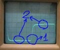
:) Believe me, I would had to do it twice anyway -as it was suggested before on this thread-. By doing it on purpose I avoided a lot of surprises and disappointments; and hopefully everything will be fixed and working for when the rest of the components arrive.

This one could be either hardware or software... You need to make sure that the sync signal at the PIC input pin is clean without any wiggles or oscillations. If the sync signal is clean then I would vote for a software problem. Posting your code would be needed to help with that.
The SYNC output looks fine, except for 2 issues: the first is a small oscillation at the beginning of the rising edge; which you can see in this picture at 500Hz...

WP_20141218_001.jpg

... and which seems to disappear above some something like 100KHZ to 500KHz, as in this picture at 500KHz...

WP_20141218_002.jpg

The second issue is the fact that the wave is not 5V peak. As you can see in the oscilloscope, which is set at 1V per division, it goes from 0.2V to around 3.8V to 4V, depending on the frequency.

I found today that I can get the PIC to read any frequency from the SYNC output by using a pull-up resistor; but I was surprised about how small the resistor needs to be -anything over 220Ω will not work-; so I'm not sure if this is a reliable solution to the problem.

I think this glitch is from the sync signal. (As I remember, the sync signal is 90 degrees out of phase with the square wave).
Hopefully, better power supply bypassing will get rid of the glitch. If not, you may have the sync signal coupling into the input of the output amp, a poor ground for the bypass capacitors or a ground loop that the sync signal is drawing current through.
You're right, the SYNC is 90 degrees out of phase. I think you might also be right (as usual :)) about this being the cause of the glitch, and also about having something to do with a bad ground. While taking those pictures above, I noticed that the glitch you see on them was gone for a moment while pushing down the left side of the LCD. Then I changed the position of the cables and the device and couldn't get the effect anymore; so I can't tell what exactly is causing the glitch.
 
Last edited:

RichardO

Joined May 4, 2013
2,270
It looks like the Sync signal has oscillation on it. I am guessing that this is a power supply bypassing issue. You should be able to see this oscillation if you look at pins 17 and 20 of the MAX038 with your scope.

If this is the case, try adding 0.1 uF ceramic capacitors directly to the power pins of the MAX038.
Add the caps to the circuit side of the PCB by soldering them between these pins:
15 and 16, 18 and 20, 17 and 18. The leads on the caps must be as short as possible (not more than 6mm).

Do you have a ground plane under the MAX038? If not, you must also solder short 24ga wires (resistor leads) between these pins:
2 and 18, 18 and 6, 15 and 9, 9 and 11.

If improving the power supply bypassing and grounds then you can isolate the Sync pin from excessive capacitive loads by putting a resistor between the Sync pin and the input of the PIC. Do this by cutting a small gap in the Sync trace near the MAX038. Then jumper over the gap by soldering a 50 to 100 ohm resistor to the ends of the traces.
Alternately, you can solder the resistor directly from the pin 14 of the MAX to the PIC input. Keep the length from the Sinc pin to the resistor short (less than 6mm).
 

Thread Starter

adam555

Joined Aug 17, 2013
858
It looks like the Sync signal has oscillation on it. I am guessing that this is a power supply bypassing issue. You should be able to see this oscillation if you look at pins 17 and 20 of the MAX038 with your scope.

If this is the case, try adding 0.1 uF ceramic capacitors directly to the power pins of the MAX038.
Add the caps to the circuit side of the PCB by soldering them between these pins:
15 and 16, 18 and 20, 17 and 18. The leads on the caps must be as short as possible (not more than 6mm).

Do you have a ground plane under the MAX038? If not, you must also solder short 24ga wires (resistor leads) between these pins:
2 and 18, 18 and 6, 15 and 9, 9 and 11.
I have a ground plane covering the whole PCB and including under the MAX. For the filtering caps I have 1uF electrolytic and 1nF ceramic in parallel right next to each rail entering the MAX. I just tried adding the extra caps you recommend, and even though it diminished the oscillation on the SYNC slightly, it doesn't get rid of it completely. I also tried with bigger 1uF, 10uF and even 100uF caps, but none of them get completely rid of the oscillation.

It might help that I just remember also seeing this oscillation when I had it all mounted in the breadboard... I think it was always there since I bought the chip.

This is a close up of the oscillation with the oscilloscope set at 0.2uS/Div and 1V/Div:

WP_20141220_002.jpg

If improving the power supply bypassing and grounds then you can isolate the Sync pin from excessive capacitive loads by putting a resistor between the Sync pin and the input of the PIC. Do this by cutting a small gap in the Sync trace near the MAX038. Then jumper over the gap by soldering a 50 to 100 ohm resistor to the ends of the traces.
Alternately, you can solder the resistor directly from the pin 14 of the MAX to the PIC input. Keep the length from the Sinc pin to the resistor short (less than 6mm).
Also tried cutting the SYNC track near the MAX and adding a 100Ω resistor, as you suggested, but it didn't have any effect on the oscillation.

It's a real pity that I can't replicate the effect I got the other day by which the oscillation disappeared when pushing down the LCD; I tried pocking every single component, and re-soldering the filtering caps, without any luck.

By the way, I just realized that the frequency at which the oscillation disappears and the PIC starts to read accurately kind of match; so, do you think this oscillation is the cause for the PIC not reading the frequency correctly, or should I go ahead and add the 220Ω pull-up resistor?
 
Last edited:

Thread Starter

adam555

Joined Aug 17, 2013
858
I forgot...

I also checked each rail to see if there was any glitch in the power supply when the oscillation occurs. There is a tiny glitch, but it is so tiny that I doubt you will be able to appreciate it in this picture at 0.5V/Div; so I'm not sure this is the problem.

WP_20141220_009.jpg
 

Thread Starter

adam555

Joined Aug 17, 2013
858
Hello,

Do you have the complete schematic?
It can be a decoupling problem.
Maybe parts have to be "isolated".

Bertus
This is the last update, which includes components that I haven't installed yet (e.g. the whole power supply), but regarding the SYNC it's basically the same of what I'm testing.

Sorry for uploading such a large image; but otherwise you wouldn't be able to read it.
 

Attachments

Thread Starter

adam555

Joined Aug 17, 2013
858
... and this is the layout in the PCB. Again, it's not exactly as the one I'm testing (e.g. the ground plane of the one I'm testing is uniform without those 4 tracks across it, and without power supply); but it's basically the same design.
 

Attachments

bertus

Joined Apr 5, 2008
22,277
Hello,

I see that you are using a switching regulator, to create a negative voltage.
Is the oscillation on the positive or negative voltage?
You could try to isolate the voltage regulator on the negative side with a resistor of 10 - 100 Ohms, between the switcher and pin 20 ( V- ) of the MAX.

Bertus
 

Thread Starter

adam555

Joined Aug 17, 2013
858
Hello,

I see that you are using a switching regulator, to create a negative voltage.
Is the oscillation on the positive or negative voltage?
You could try to isolate the voltage regulator on the negative side with a resistor of 10 - 100 Ohms, between the switcher and pin 20 ( V- ) of the MAX.

Bertus
At the moment there is no power supply on the PCB I'm testing; I'm supplying the +5V and -5V by hooking a bench power supply, which is regulated for up to 7.5A on the +5V and 300mA on the -5V.

The oscillation on the main output is on the bottom cycle of the square wave, and on the SYNC is at the beginning of the rising edge; so I guess that makes it rather the -5V rail.

If you are referring the tiny glitch marked with a circle on my last picture; this one is present on both +5V and -5V rails.
 

Thread Starter

adam555

Joined Aug 17, 2013
858
Sorry, I made a mistake when I said the oscillation disappeared the other day when pushing the LCD; it was a completely different glitch.

As you can see in the attached pictures, the one marked as "1" is the oscillation, and the one marked as "2" is the one that disappeared when pocking the LCD, and which is already fixed.
 

Attachments

RichardO

Joined May 4, 2013
2,270
How odd. The oscillation shown in post #103 nearly triples (from 10 MHz to 30 MHz) in frequency over a 1 uS period. I have no idea why. :(

Here are some wild thoughts...
Maybe pin 3 of the PIC is somehow set as an output such that it is fighting the Sync signal from the MAX038. How do the waveforms compare at the PIC input with and without the 100 ohm resistor?

... Or maybe the power or ground of the PIC is not really connected and the Sync signal is trying to power the PIC through the pin 3 input.
What do the power and ground look like right on the pins of the PIC (as apposed to the traces going to the PIC)?
 

Thread Starter

adam555

Joined Aug 17, 2013
858
How odd. The oscillation shown in post #103 nearly triples (from 10 MHz to 30 MHz) in frequency over a 1 uS period. I have no idea why. :(

Here are some wild thoughts...
Maybe pin 3 of the PIC is somehow set as an output such that it is fighting the Sync signal from the MAX038. How do the waveforms compare at the PIC input with and without the 100 ohm resistor?
This picture is with the 100Ω resistor and the probe on the PIC's side...

WP_20141220_010.jpg

This one is also with the resistor but with the probe on the MAX's side...

WP_20141220_011.jpg

This one is without the resistor -directly connecting the SYNC output to the pin 3 of the PIC-...

WP_20141220_012.jpg

And this last one is with an extra 100nF ceramic capacitor on the +5V rail. As you can see, the oscillation is shorter, but not completely gone; and the same happens even with larger caps up to 100uF.

WP_20141220_013.jpg

... Or maybe the power or ground of the PIC is not really connected and the Sync signal is trying to power the PIC through the pin 3 input.
What do the power and ground look like right on the pins of the PIC (as apposed to the traces going to the PIC)?
I just tested it without the track connecting the SYNC to the PIC, since I had cut the track before, and the oscillation is still there even without anything connected to it but the oscilloscope's probe.
 
Last edited:

RichardO

Joined May 4, 2013
2,270
"And this last one is with an extra 100nF ceramic capacitor on the +5V rail. As you can see, the oscillation is shorter, but not completely gone; and the same happens even with larger caps up to 100uF."
Since the oscillation changes with power supply bypassing then I believe it is a power bypassing problem. Are your 100 nF caps ceramic? They _must_ be ceramic to work -- film caps have way too much inductance. You need _both_ the ceramic cap and a large electrolytic cap near each of the MAX038 power pins. The ceramic cap makes the power supply low impedance at high frequencies and the electrolytic helps to keep the impedance low at lower frequencies.

Your schematic shows this kind of power bypassing for the THS4222. Do the same thing for the MAX038.

By the way, I noticed that the Sync signal trace can be made a lot shorter by routing it under the PIC. Shorter traces are always better than longer traces.
 

Thread Starter

adam555

Joined Aug 17, 2013
858
I found this other configuration on the datasheet; they are using different caps for the +5V and the DV+, plus a 100Ω resistor before the DV+.

WP_20141220_011 copy.jpg
 

Thread Starter

adam555

Joined Aug 17, 2013
858
"And this last one is with an extra 100nF ceramic capacitor on the +5V rail. As you can see, the oscillation is shorter, but not completely gone; and the same happens even with larger caps up to 100uF."
Since the oscillation changes with power supply bypassing then I believe it is a power bypassing problem. Are your 100 nF caps ceramic? They _must_ be ceramic to work -- film caps have way too much inductance. You need _both_ the ceramic cap and a large electrolytic cap near each of the MAX038 power pins. The ceramic cap makes the power supply low impedance at high frequencies and the electrolytic helps to keep the impedance low at lower frequencies.

Your schematic shows this kind of power bypassing for the THS4222. Do the same thing for the MAX038.
I have a 1uF electrolytic cap fixed on the PCB right next to each power supply pin, and the extra one I added were 100nF ceramic. I tried adding the same extra 100nF ceramic to the -5V rail but it had absolutely no effect; it's seems to be the +5V rail that affects the oscillation when changing the caps.

By the way, I noticed that the Sync signal trace can be made a lot shorter by routing it under the PIC. Shorter traces are always better than longer traces.
Yes, but I just tested the SYNC without connecting it to anything -with only the oscilloscope probe directly connected to it- and it had no effect on the oscillation.

I'm starting to think this chip is faulty. :(
 

RichardO

Joined May 4, 2013
2,270
"I'm starting to think this chip is faulty. :("
Sorry, I don't think this is likely. I still will wager on a power supply bypassing issue.

Remember that the scope probe puts a capacitive load on a signal. A times one probe puts a huge capacitive load on a high speed signal like the Sync signal or the THS4222 output.
 

Thread Starter

adam555

Joined Aug 17, 2013
858
It worked!!!!

I changed everything to match that other configuration from the datasheet; got rid of the 1uF electrolytics and replaced them for 100nF ceramics on both rails, added a 100Ω resistor before the DV+ digital supply plus added another 100nF ceramic to it, and now both waveforms are smooth as a baby's butt! :)

Top is the main output, bottom is the SYNC... and the PIC is also reading the right frequency...

WP_20141221_002.jpg

I can't believe I'm going to finish this project without any glitch... well, I let you know how the new power supply is working as soon as I get the order; which might take a while, since I'm buying it all from DigiKey and I need to fill an order for €65 to get free shipping; otherwise they ask for €18 in P&P, which is outrageous!
 

RichardO

Joined May 4, 2013
2,270
Good to see it is now working!

I suspect that the 1 uF caps were electrolytic caps and replacing them with 0.1 uF ceramic caps got rid of the Sync output oscillations and that the 100 ohm/0.1 uF fix got rid of the glitch in the square wave. Am I right?

The switching power supply is tricky enough to justify its own thread. ;)
 
Top