MAX038 Function Generator Design

Thread Starter

adam555

Joined Aug 17, 2013
858
Hi,

I'm in the process of designing a small function generator based on the MAX038CPP -a sort of handheld device with just this chip and a PIC to output the frequency to a small LCD. The PIC will also control the form of the output wave, since you can do it digitally, but I'm not sure if I can also do the same with the capacitors for selecting the range; so my first question is:

1 - Is there any way to digitally switch between the capacitors for selecting the frequency range? I mean, having a button or two connected to the PIC which would emulate the function of a rotary switch.

2 - My second question is about the Phase Detector function of the MAX038: would I be able to add this in any useful way without connecting any external device; like getting a modulated frequency or any other function that could be added to this design? I already read the section about this function on the datasheet, but I can't figure out what use I can get out of this function without an external input.

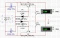
3 - I've already chosen the power supply, but I've been think about this for a long time: is there any simple way to double the +5v supplied by an USB port -getting 10v out of it-? For example, the equivalent of this simple AC circuit, but for DC:


Thanks in advance for your help.
 

RichardO

Joined May 4, 2013
2,270
#1 The best choice is a low voltage/power relay. An analog switch can be used but the on resistance causes a discontinuity in the peaks of the triangle and sine waves. Any switch leakage causes an asymmetry of the waveforms.

#2 The phase comparator is normally used as part of a phased locked loop. This signal is in quadrature to the usual square wave output. Sometimes that might be useful. I have used this signal as one input of a trigger/gate circuit...

#3 A voltage inverter chip like an ICL7660 is one example. Be warned that the "5 volts" from a USB port isn't 5 volts.
 

Thread Starter

adam555

Joined Aug 17, 2013
858
The design has 4 capacitors to select between ranges; it would be great if I could get one of those relays with 4 positions.

One of the options I considered was to double the USB 5v and then split it with the small circuit below to supply the MAX038, which ideally needs +5v and -5v.
 

Attachments

Thread Starter

adam555

Joined Aug 17, 2013
858
Been looking for relays and the smallest ones I found are going to take a lot of space; specially when using 4. Space was one of the reasons why I didn't want to use a rotary switch.
 

crutschow

Joined Mar 14, 2008
34,409
For switching the caps you might try a low resistance CMOS switch such as one of these. They have a maximum ON resistance of 10 ohms, which should have only a minor effect on the chips oscillator frequency, although the added switch capacitance will have some effect depending upon the highest frequency you want.

Edit: Upon further reflection you don't need an analog switch, you just need a small N-MOSFET switch to ground, such as these, for example, which come two in a small package and have an ON resistance of only 100 milliohms.
 
Last edited:

crutschow

Joined Mar 14, 2008
34,409
The highest frequency will be 20Mhz, for which I need to use a 20pF capacitor.
A FET or analog switch could be a problem for that. For example, the MOSFET array I suggested in post #7 has a source output capacitance of 50pF. This device has a maximum output capacitance of 25pF. There likely are even lower capacitance devices if you search.
 

Thread Starter

adam555

Joined Aug 17, 2013
858
Never dealt with this type of issue before. So if I understand correctly the problem is that the output capacitance of the switch will be added to the capacitor I'm using, and therefore I will not reach the maximum expected frequency.

So to use one of these switches I need to find the one with the lowest output capacitance and account for it -added to the capacitor it's switching- in order to calculate the desired output frequency.
 

atferrari

Joined Jan 6, 2004
4,767
Switching capacitors in circuit.

I recall solving a similar problem twice.

First, many many years ago, with a generator based on the XR2206 or maybe the SN76477; not sure. No micro in charge (they were a rarity and were not aware of me yet :p).

Second, to smooth the output of switched-capacitors (LF100) filters in a three-phase low frequency generator. A micro used to conduct the circus.

The first, required one capacitor at a time, switched on. The second (maybe I was becoming a little smarter ??) switched capacitors progressively in parallel to one which was always on (in my case, the one with the smaller value).

In both cases I used a similar approach as per the attached circuit. I always expect the professionals to criticize this but in my second design it really seemed to work OK. ¡Oh sí!

The pull down resistors I effectively included them in my design.

Obviously you need some I/O pins to activate the transistors.

PD: I recall testing the ICL8038 which is still somewhere around here. It run close to hot. :( They said it was normal. (?) o_O
 

Attachments

Thread Starter

adam555

Joined Aug 17, 2013
858
Me gusta tu solución; sobre todo porque no necesito comprar componentes extra para probarla. ;)

And what a coincidence! Did another function generator last year with the ICL8038 -but with a rotary switch- and this project was meant to be with the XR2206 -but bought it really cheap on ebay from China and the secondary oscillator doesn't work, plus it just refuses to work above half the rated voltage.

Anyway, thanks. I'll try your circuit tomorrow.
 

crutschow

Joined Mar 14, 2008
34,409
Never dealt with this type of issue before. So if I understand correctly the problem is that the output capacitance of the switch will be added to the capacitor I'm using, and therefore I will not reach the maximum expected frequency.

So to use one of these switches I need to find the one with the lowest output capacitance and account for it -added to the capacitor it's switching- in order to calculate the desired output frequency.
It's not the MOSFET that's ON that's the problem since it has essentially no capacitance when it's ON. It's the OFF devices that will generate a capacitance to ground since each of the transistors' capacitance is in series with the capacitors that are off. You thus have a number of parallel MOSFET capacitances that will add to the total.
 

Thread Starter

adam555

Joined Aug 17, 2013
858
I just tested atferrari's circuit to switch between the capacitors with transistors -I had to change them for PNP (I'm using BC327) as the external capacitor connection current was negative, and in general I think it's working well.

I didn't use the base resistors from the original circuit; as I need to do the biasing calculations first, which takes beginners like me a lot of time and effort, so I hope this is not influencing the result in a negative way.

Whether I use this circuit or the chip proposed by crutschow I'm going to get this output capacitance; according to the datasheet these transistors produce 12pF at -10V and 1Mhz. But I guess that, whether I end up using the chip or the transistor array, with a little tuning I could account for it.

The highest frequency I reached with the smallest capacitor (20pF) was 5Mhz -instead of the maximum 20Mhz without the transistor array- but anyway the output amplitude begins to drop, with or without transistors, above 2Mhz; so I'm not sure it's worth the effort trying to achieve the 20Mhz. It's just meant to be a for home use; something handy rather than precise.

Sometimes I also get some distortion on the output, which seems to go away if I start poking the components; so I guess it's because I have them all in a breadboard, rather than a design flaw.

Anyway, any further suggestions will be more than welcome.

Thanks.
 

RichardO

Joined May 4, 2013
2,270
I just tested atferrari's circuit to switch between the capacitors with transistors -I had to change them for PNP (I'm using BC327) as the external capacitor connection current was negative, and in general I think it's working well.

I didn't use the base resistors from the original circuit; as I need to do the biasing calculations first, which takes beginners like me a lot of time and effort, so I hope this is not influencing the result in a negative way.

Whether I use this circuit or the chip proposed by crutschow I'm going to get this output capacitance; according to the datasheet these transistors produce 12pF at -10V and 1Mhz. But I guess that, whether I end up using the chip or the transistor array, with a little tuning I could account for it.

The highest frequency I reached with the smallest capacitor (20pF) was 5Mhz -instead of the maximum 20Mhz without the transistor array- but anyway the output amplitude begins to drop, with or without transistors, above 2Mhz; so I'm not sure it's worth the effort trying to achieve the 20Mhz. It's just meant to be a for home use; something handy rather than precise.

Sometimes I also get some distortion on the output, which seems to go away if I start poking the components; so I guess it's because I have them all in a breadboard, rather than a design flaw.

Anyway, any further suggestions will be more than welcome.

Thanks.
Some comments;

PNP or NPN should not matter since the charging signal is capacitor coupled into the transistor (by the timing cap). I seem to remember that the bipolar transistor causes some kind of distortion in the triangle wave but it has been a _very_ long time since I tried this.

Diode junctions have more capacitance at lower reverse bias so I would expect more capacitance than the 12 pF at the voltage in your circuit. If I were doing this I would try a high speed switching transistor such as a 2N2369. A microwave transistor such as a 2SC3356 has much lower capacitance but its other characteristics may not be right.

The output amplitude should _not_ be dropping above 2 MHz. I suspect a circuit layout or measurement error is causing your problem.

At these frequencies, wiring on a solderless breadboard is very tricky. All leads must be short, no ground loops, short power supply bypass distances, etc, etc. See the attachment.

The document I attached was actually written with the MAX038 in mind!
 

Attachments

Thread Starter

adam555

Joined Aug 17, 2013
858
Some comments;

PNP or NPN should not matter since the charging signal is capacitor coupled into the transistor (by the timing cap). I seem to remember that the bipolar transistor causes some kind of distortion in the triangle wave but it has been a _very_ long time since I tried this.
Thanks a lot for pointing this out. You had no idea what a headache you saved me from: I've been trying for the last hour to figure out how to get from the PIC the negative voltage needed to drive the PNP transistors -without adding extra transistors-.

For some reason I was under the impression that the current could only flow in one direction between Collector and Emitter; but you're right, it works exactly the same with NPN.

The output amplitude should _not_ be dropping above 2 MHz. I suspect a circuit layout or measurement error is causing your problem.
I always get this drop in amplitude with every function generator I tested near their limit -whether it is the 300Khz of the ICL3038, the 1Mhz of the XR2206, or in this case the 20Mhz of this MAX038- for this reason I thought it was normal; that all do it when pushed towards the limit.

At these frequencies, wiring on a solderless breadboard is very tricky. All leads must be short, no ground loops, short power supply bypass distances, etc, etc. See the attachment.

The document I attached was actually written with the MAX038 in mind!
I was counting with some of these effects; since while testing I don't cut the component's leads, avoid loops and long distances, and so on... I'll definitely have a look at that document to avoid this things as much as possible in the future.
 
Last edited:

Thread Starter

adam555

Joined Aug 17, 2013
858
Just finished making all parts work together, but now I ran into a couple more doubts and issues:

- Should I use resistors between the different ICs? I mean, I put 10k resistors -just in case- between the MAX038 and the PIC's I/O pins; but I chose the value arbitrarily and I'm not even sure they are needed.

- Last year I did another function generator from a design I found on the internet for the ICL3038, and it had an addition amplifying stage at the end; do all these function generators need this additional stage?

- I also need the Frequency Counter, controlled by the PIC, to detect more than 700 Mhz. But I guess that's a question for the Microcontrollers forum, so I'm already asking here: High Frequency Counter with a 10Mhz PIC
 

RichardO

Joined May 4, 2013
2,270
10K ohms for the resistors sounds high. If the value is too high then any input current flowing through the resistor prevents getting proper logic levels to the input. This is very bad as it will run the input gate circuit in the linear region causing it and the rest of the IC to get hot.

A buffer amplifier is not always needed but the better the output circuit the more useful the generator will be.

The output of the MAX038 is 2 volts peak to peak. It is not likely that is exactly what you need to do your testing. Because of this the output needs have an adjustable amplitude. You want to be able to set the output amplitude from a few millivolts to several volts. The get the small voltages you will likely need a step attenuator.

In addition, the output needs to have a low impedance to drive some circuits. Typically this is 50 ohms but 600 ohms is good enough for audio frequencies. The output has to withstand a short circuit. A reasonable IC for the output amp is the LM6181 in an 8-pin DIP.

In addition to measuring frequency, you also want to be able to measure period. For example, with a 1 second gate a 150 HZ signal will show as "150 Hz" but as a period it will show "6.6666667 mS". As you can see, the period has much more resolution in the measurement; 8 digits versus 3 digits. In addition, the period will be measured much faster --. as quick as 1/150th of a second.
 

Thread Starter

adam555

Joined Aug 17, 2013
858
10K ohms for the resistors sounds high. If the value is too high then any input current flowing through the resistor prevents getting proper logic levels to the input. This is very bad as it will run the input gate circuit in the linear region causing it and the rest of the IC to get hot.
I left the 10k resistors because it allows enough current for the inputs on the MAX to work. What I was trying to do was to draw as little current as possible from the PIC's outputs. But as I said, I'm not sure if this is the way to do it, or if they are even necessary at all; as both the PIC outputs and the MAX inputs are 5v.

What would you recommend?

A buffer amplifier is not always needed but the better the output circuit the more useful the generator will be.

The output of the MAX038 is 2 volts peak to peak. It is not likely that is exactly what you need to do your testing. Because of this the output needs have an adjustable amplitude. You want to be able to set the output amplitude from a few millivolts to several volts. The get the small voltages you will likely need a step attenuator.

In addition, the output needs to have a low impedance to drive some circuits. Typically this is 50 ohms but 600 ohms is good enough for audio frequencies. The output has to withstand a short circuit. A reasonable IC for the output amp is the LM6181 in an 8-pin DIP.

In addition to measuring frequency, you also want to be able to measure period. For example, with a 1 second gate a 150 HZ signal will show as "150 Hz" but as a period it will show "6.6666667 mS". As you can see, the period has much more resolution in the measurement; 8 digits versus 3 digits. In addition, the period will be measured much faster --. as quick as 1/150th of a second.
Thanks for all that info; specially the part about measuring the period, which I forgot to add.
 

RichardO

Joined May 4, 2013
2,270
The MAX038 A0 and A1 inputs are spec'ed at +/- 5 uA at 25 deg. C. This current will double about every 10 degrees. That would make the current more like 40 ua at 55 degrees ambient and maybe much more than that depending on how hot the chip gets. So, the _best_ case 40 uA times 10K is 400 mV dropped across the resistor. This is marginal as an input voltage to the MAX038 since it allows a maximum of 0.8 volts as a logic low.

If the PIC and the MAX038 are powered from the same power supply then the resistor is not needed -- I would not use one myself. If you want to do "belt and suspenders" then you should go with something like a 1K resistor, maximum.
 
Top