 Facebook
 Google
 GitHub
 Linkedin
Hi,
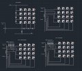
on internet I found different diagrams how to connect 4x4 matrix keyboard to a microcontroller.
this are the 4 different diagrams I found.
1st diagrams using ADC and voltage divider is understood 100%
2. diagram with no resistors I thin is false since having no sink resistors on the output means that voltage will stay even when pin will transition from logic 1 to logic 0.
3rd diagram with pull down resistors on the output pins is actually what I am thinking to make.
4th diagram is actually same as 3rd only in reverse and I think we can use internal weak pull ups instead of one on the PCB?
Do I understand those diagrams correctly?
Attachments
-
 96.6 KB Views: 10


