 Facebook
 Google
 GitHub
 Linkedin
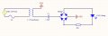
I am trying really hard to wrap my brain around what is going on in the very simple attatched schematic. I have two very conflicting models of behavior, and I am hoping someone can point out my errors! The goal is to model the current and power through the LED array with respect to time. Let me walk through the general set-up, then I will use specific values.
Using rms Averages and Static Xc and leaving the Diodes Out, the simple formula is derived as follows:
Xc = 1 / (2Pi * F * C)
Z = (Xc^2 + R^2)^.5
Irms = Vrms/Z
Pavg = Irms * Vrms
Using: C = 1.5uF Vrms = 120 Freq = 60hz and R = 200 nLEDs = 50 ohms Test Period = 3Pi Step = Pi/150 this model predicts:
Xc = 1/(2Pi * 60 * .0000015) => 1768
Z = (1768^2 + 200^2)^.5 = 1779.66
Irms = 120/1779.66 = 67.429mA
Pavg = .067429 * 120 = 8.09W
But obviously these calculations do not take the LEDs into account, but rather reflect what one would assume would be the maximum current/power of the series RC portion of the circuit.
Using a PC to plot V(t), I(t), P(t) for both the circuit and the LEDs I made the following assumptions:
1) No current flows through the LEDs when V(t) < (Vf * Number of Series LEDs).
2) V(t) = Vrms * 2^.5 Sin(t)
3) The Reactance of the transformer is not an influence on the circuit.
I derived two models:
Model 1: The change in voltage across Cs for any given period of time is related to the current flow by dQ = dV * C, and dQ/dT = Current. So, if we step through Vmax * Sin(t) for t=0 to 2Pi by Pi/Steps and calculate the change in charge on the Capacitor we should be able to determine the Current through the LEDs. This obviously is a discontinuous function as V(t) < Vf => Current = 0 (by assumption), but the current should "ramp quickly" after V(t) > Vf. From this point the current becomes continuous until V(t) = Vf again. I_LED = (V(t) - Vf)/R. If I_LED > I(t) (calculated from dV*C) then I_LED = dV*C/dT.
Using: C = 1.5uF Vrms = 120 Freq = 60hz and R = 200 ohms nLEDs = 50 Test Period = 3Pi Step = Pi/150 this model predicts:
Peak Led Power = 0.331W
Avg Led Power = 52.593mW
Avg Resistor Power = 0.103mW
Peak Led Current = 2.207mA
Avg Led Current = 0.351mA
These calculations DO NOT appear to correspond with actual circuit tests!
Model 2: The impedance, Z of the circuit should relate V(t) = Vmax * Sin(t) to the Current by calculating the phase angle as follows:
Xc = 1 / (2Pi * F * C)
Z = (R^2 + (Xc)^2)^.5
Phase Angle = - aSin(Xc/Z)
I(t) = (Vmax/R) * Sin(t - Phase Angle)
Using: C = 1.5uF Vrms = 120 Freq = 60hz and R = 200 ohms nLEDs = 50 Test Period = 3Pi Step = Pi/150 this model predicts:
Peak Led Power = 7.376W
Avg Led Power = 1282.819mW
Avg Resistor Power = 60.166mW
Peak Led Current = 49.171mA
Avg Led Current = 8.552mA
These calculations appear closer to observations of the actual circuit, but, sadly changing the capacitor to 0.2uF and repeating the calculations:
Using: C = 0.2uF Vrms = 120 Freq = 60hz and R = 200 ohms nLEDs = 50 Test Period = 3Pi Step = Pi/150 this model predicts:
Peak Led Power = 7.041W
Avg Led Power = 1257.589mW
Avg Resistor Power = 57.135mW
Peak Led Current = 46.940mA
Avg Led Current = 8.384mA
And these calculations ABSOLUTEY do not match observations of the actual circuit. I am at a loss. Perhaps I need to model the diodes using variable Vf? Perhaps I have missed something even more fundamental. Any thoughts would be helpful!
Using the 1.5uF Capacitor and the other common elements except connecting two strands of 50 series leds in parallel, there is no visible difference in the brightness of the strands. That is both strands appear to the eye to be "X bright". When one of the strands is disconnected, the other does not appear to "brighten"; this suggests that the "shared current" is similar to the "Un-shared current", which suggests that the circuit current is limitted purely by resistance; however, this theory does not hold, because when 1 strand uses 1 100 ohm resistor and the other strand uses a 200 ohm resistor, again, there is no visible difference in brightness.
Thanks in advance for any help.
Fish
Attachments
-
 207.3 KB Views: 52


