Facebook
 Google
 GitHub
 Linkedin
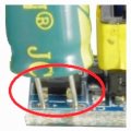
If you look at the photo, you will see markings that point out the input (blue circle) and output (green circle) I assume the "L & N" on the input is for AC input, and the "+ & -" is for the DC input which the text on the one photo explains. But when one looks at the bottom of the PCB, There is "a & -" marking with "DC310V" (red circle). These two points are connection points for the onboard 4.7uf capacitor.
Does anyone know why these markings are on the PCB Is this possibly a second DC voltage in point, or maybe a "test point" indication
Does anyone know why these markings are on the PCB
Is this possibly a second DC voltage in point, or maybe a "test point" indicationAttachments
-
 138.4 KB Views: 21
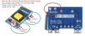
 There is a MB10F-13 BRIDGE RECTIFIER (1PH 1KV 800MA) SMD rectifier under the capacitor. You can just make it out in the attached photo.