Facebook
 Google
 GitHub
 Linkedin

Problem
The schematic can be viewed here: http://imgwiz.com/images/2013/11/13/1fqrc.png
I require a digitally adjustable sine-wave generator in the range of 100kHz-10MHz. The frequency is set by "switching" in and out 8 different resistors using analog switches.
I'm having trouble calculating the resistors because
Some Math...
Given the 8 resistors, this allows 256 steps. The frequency needs to follow the curve:
\(f=f(x)=fmin*m^{x}\) with \(0\leq x\leq 256\)
where:
\(m=\sqrt[n]{\frac{fmax}{fmin}}\)
n = 8 (because we're using 8 bits)
fmin = 100kHz
fmax = 10MHz
The frequency of the wien-oscillator can be calculated with the usual formula:
\(f0=\frac{1}{2\pi RC}\)
Schematic
The schematic can be viewed here: http://imgwiz.com/images/2013/11/13/1fqrc.png
I've boxed the resistors that end up being parallel with each other.
The core of the oscillator is a wien-bridge-oscillator. For simplicities sake, assume that's all it is (there's some feedback circuitry for high precision waveform and amplitude adjustment but has nothing to do with this problem).
Graphs
I've generated some graphs with what it currently looks like, and what I want it to look like.
This is what it currently looks like.

This is what I want it to look like. I used the formulas I specified above to generate the graphs below.
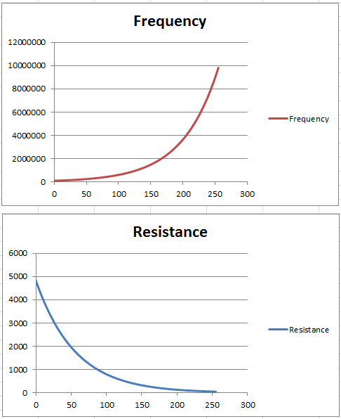
The resistance is the total resistance. How do I now go about splitting up the 256 values seen in the last graph into 8 separate resistor values which can be switched in and out by the analog switches?
The schematic can be viewed here: http://imgwiz.com/images/2013/11/13/1fqrc.png
I require a digitally adjustable sine-wave generator in the range of 100kHz-10MHz. The frequency is set by "switching" in and out 8 different resistors using analog switches.
I'm having trouble calculating the resistors because
- The frequency needs to be adjusted logarithmically and not linearly. This is so the frequency steps are appropriately scaled to the magnitude of the frequency and appear even (more information about that in the "graphs" section)
- The resistors aren't in series, they're in parallel. This is to minimize tolerances of the resistors and analog switches, but it makes calculating them far more difficult.
Some Math...
Given the 8 resistors, this allows 256 steps. The frequency needs to follow the curve:
\(f=f(x)=fmin*m^{x}\) with \(0\leq x\leq 256\)
where:
\(m=\sqrt[n]{\frac{fmax}{fmin}}\)
n = 8 (because we're using 8 bits)
fmin = 100kHz
fmax = 10MHz
The frequency of the wien-oscillator can be calculated with the usual formula:
\(f0=\frac{1}{2\pi RC}\)
Schematic
The schematic can be viewed here: http://imgwiz.com/images/2013/11/13/1fqrc.png
I've boxed the resistors that end up being parallel with each other.
The core of the oscillator is a wien-bridge-oscillator. For simplicities sake, assume that's all it is (there's some feedback circuitry for high precision waveform and amplitude adjustment but has nothing to do with this problem).
Graphs
I've generated some graphs with what it currently looks like, and what I want it to look like.
This is what it currently looks like.
This is what I want it to look like. I used the formulas I specified above to generate the graphs below.
The resistance is the total resistance. How do I now go about splitting up the 256 values seen in the last graph into 8 separate resistor values which can be switched in and out by the analog switches?
Last edited: