Manual DAC - help calculate resistors?

Thread Starter

TheComet

Joined Mar 11, 2013
88
Problem

The schematic can be viewed here: http://imgwiz.com/images/2013/11/13/1fqrc.png

I require a digitally adjustable sine-wave generator in the range of 100kHz-10MHz. The frequency is set by "switching" in and out 8 different resistors using analog switches.

I'm having trouble calculating the resistors because

  1. The frequency needs to be adjusted logarithmically and not linearly. This is so the frequency steps are appropriately scaled to the magnitude of the frequency and appear even (more information about that in the "graphs" section)
  2. The resistors aren't in series, they're in parallel. This is to minimize tolerances of the resistors and analog switches, but it makes calculating them far more difficult.
So that's what I need help with: Figuring out the values of all 8 resistors with the following constraints.


Some Math
...

Given the 8 resistors, this allows 256 steps. The frequency needs to follow the curve:

\(f=f(x)=fmin*m^{x}\) with \(0\leq x\leq 256\)

where:
\(m=\sqrt[n]{\frac{fmax}{fmin}}\)

n = 8 (because we're using 8 bits)
fmin = 100kHz
fmax = 10MHz

The frequency of the wien-oscillator can be calculated with the usual formula:

\(f0=\frac{1}{2\pi RC}\)


Schematic

The schematic can be viewed here: http://imgwiz.com/images/2013/11/13/1fqrc.png

I've boxed the resistors that end up being parallel with each other.

The core of the oscillator is a wien-bridge-oscillator. For simplicities sake, assume that's all it is (there's some feedback circuitry for high precision waveform and amplitude adjustment but has nothing to do with this problem).


Graphs


I've generated some graphs with what it currently looks like, and what I want it to look like.

This is what it currently looks like.


This is what I want it to look like. I used the formulas I specified above to generate the graphs below.
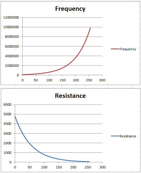


The resistance is the total resistance. How do I now go about splitting up the 256 values seen in the last graph into 8 separate resistor values which can be switched in and out by the analog switches?
 
Last edited:

MrChips

Joined Oct 2, 2009
35,296
ooh! That's a tough one.
I don't think you can do this by switching resistors.
The only solution I can think of is to use a microcontroller.
Create a lookup table with 256 entries. The value in each entry will be a number that controls the frequency of your sinewave using a timer module.
 

Thread Starter

TheComet

Joined Mar 11, 2013
88
I don't think you can do this by switching resistors.
Sure it's possible with resistors, I'm just caught up on the math because they're parallel, and it involves 8 unknown values and a total of 256 equations... (as far as I can see)

The only solution I can think of is to use a microcontroller.
Create a lookup table with 256 entries. The value in each entry will be a number that controls the frequency of your sinewave using a timer module.
A micro controller manually generating a sine wave at 10 MHz? I don't see that happening, most micro controllers aren't clocked much higher than 40 MHz. Producing a pure sine wave at those frequencies would be impossible, that's why I'm working with an external oscillator.

My circuit already is controlled by a micro controller (as can bee seen by the /SYNC, SCLK, and DIN pins on N1).


Was my post unclear? Do I need to re-formulate my question?
 
Last edited:

kubeek

Joined Sep 20, 2005
5,796
I don´t think that the fact they are in parallel matters, because you can look at the resistors as conductances that simply add up, then inverse the value to get total resistance.

Now let´s get started on the math. If you got 8 variables, you need 8 equations to solve for all of them. Now if you got 256 of these equations, unless the rest of them are are "equivalent" to the 8(..to a linear combination of remaining 8) they will contradict any other solution you find.
Linearity is the key here, 8bit linear DAC works just because all the steps are linear.
Thus I pronounce this a dead case, but I´m ready to be proven wrong ;)
 

Thread Starter

TheComet

Joined Mar 11, 2013
88
The oscillator needs to have extremely low distortion (<0.01% THD) and simultaneously span a huge frequency range (factor 100). No other oscillator comes into question.

[EDIT]
Thus I pronounce this a dead case, but I´m ready to be proven wrong
I almost feared this would be the case; I'm beginning to agree with you the more crunch the numbers. I suppose I can approximate the curve as much as possible...
 

ScottWang

Joined Aug 23, 2012
7,509
If we using the pure hardware to convert Digital To Analog, and calcalting the Frequency and the numbers of dots of waveform:

1Mhz clock and 8 dots of waveform : 1000000/8 = 125Khz
1Mhz clock and 16 dots of waveform : 1000000/8 = 62.5Khz
1Mhz clock and 32 dots of waveform : 1000000/8 = 31.25Khz
1Mhz clock and 64 dots of waveform : 1000000/8 = 15.625Khz
1Mhz clock and 128 dots of waveform : 1000000/8 = 7.8125Khz
1Mhz clock and 256 dots of waveform : 1000000/8 = 3.90625Khz

10Mhz clock and 8 dots of waveform : 1000000/8 = 1.25Mhz
10Mhz clock and 16 dots of waveform : 1000000/8 = 625Khz
10Mhz clock and 32 dots of waveform : 1000000/8 = 312.5Khz
10Mhz clock and 64 dots of waveform : 1000000/8 = 156.25Khz
10Mhz clock and 128 dots of waveform : 1000000/8 = 78.125Khz
10Mhz clock and 256 dots of waveform : 1000000/8 = 39.0625Khz

40Mhz clock and 8 dots of waveform : 1000000/8 = 5Mhz
40Mhz clock and 16 dots of waveform : 1000000/8 = 2.5Mhz
40Mhz clock and 32 dots of waveform : 1000000/8 = 1.25Mhz
40Mhz clock and 64 dots of waveform : 1000000/8 = 625Khz
40Mhz clock and 128 dots of waveform : 1000000/8 = 312.5Khz
40Mhz clock and 256 dots of waveform : 1000000/8 = 156.25Khz
 

Thread Starter

TheComet

Joined Mar 11, 2013
88
I believe I said back in post #2 that you cannot do this by switching resistors.
Yes, you did, but you neglected to provide any explanation as to why it's not possible. Saying it's "not possible" isn't entirely correct, because it's obviously possible if the frequency is scaled linearly (as proven in the first and second graph I posted in OP). As kubeek pointed out, a logarithmic frequency scale can't be achieved.

I'm sorry if I appear a little frustrated, I didn't mean to attack you. This project is kind of under pressure, and I simply wanted some answers.

@ScottWang

The problem with this is your output waveform is going to have a very high THD (I need +80dB attenuation between harmonics), because it will look something like the following.


ScottWang

Joined Aug 23, 2012
7,509
@ScottWang

The problem with this is your output waveform is going to have a very high THD (I need +80dB attenuation between harmonics), because it will look something like the following.

It just let you to see how high the frequency that you can reach, the output waveform will be rough as saw that if the dot are too less, if you want to make it more smoothly, then you can using the RC integration circuit to modify the waveform.

But if the waveform needs more smoothly then the dot will be need more and the output frequency will be more lower.
 

crutschow

Joined Mar 14, 2008
38,936
You might consider a dual logarithmic digital pot. They don't have good absolute resistance tolerance but two on the same chip might be reasonably well matched.
 

Thread Starter

TheComet

Joined Mar 11, 2013
88
You might consider a dual logarithmic digital pot. They don't have good absolute resistance tolerance but two on the same chip might be reasonably well matched.
That's a good idea.

I can't seem to find any ICs that would be capable of:


  • 56Ω - 5.6kΩ
  • Resistive response up to 10 MHz
Do you have any recommendations?
 

Thread Starter

TheComet

Joined Mar 11, 2013
88
how about changing the rest of the components to match the pot that you have available?
The frequency needs to be adjustable from 100kHz to 10MHz. That's a factor of 100. Since the resistance has inverse linearity to the frequency, the pot will always be required to change with a factor of 100 as well, regardless of how I adjust the other components.
 

GopherT

Joined Nov 23, 2012
8,009
Are you planning to sweep that frequency range or just sit on one frequency in the range. If sitting on one, then you can have a selector switch to pick a capacitor for a narrow range and allow the pot to cover a 10x range. Or, a picrocontroller can use a multiplexer or bilateral switch to select the correct capacitor for your desired frequency range.
 

crutschow

Joined Mar 14, 2008
38,936
The best I found in a cursory Google search is this from Analog Devices. It's a dual digital controlled resistor with 1024 steps, available with 25kΩ maximum resistance. You could perhaps use that to generate a coarse 256 step (or shorter) approximation of a logarithmic sequence by proper selection of the step size. Note that one limitation is that the resistor voltage must stay within the power supply range of 0V to 5.5V.
 

WBahn

Joined Mar 31, 2012
33,332
Sure it's possible with resistors, I'm just caught up on the math because they're parallel, and it involves 8 unknown values and a total of 256 equations... (as far as I can see)
So you have 256 equations and 8 unknowns.

Are you SURE a solution exists?

Usually as soon as you have one more equation than unknown you have the possibility that no solution exists. Here you have that in spades.

So unless the bulk of your equations are redundant....
 
Top