The Langlois design also puts forward a modulated capacitor discharge method that makes for much smoother finish.
His first idea was simply a cap discharge and charge with no regulated switching at all, just various cap values switched.
Max.
Thats one of the problems with Flemming and his two books. With each printing he updates and never posts the update in his forum. I have edition #1, printed in 2005, was one of his first customers, and there been 4 or 5 editions since. Makes it fun when everyone is talking about a different circuit.
I think basically that is what I said or at least meant, "Advance the electrode, as soon as the voltage collapses (shorts), then retract until the voltage builds and advance over again"
His LM339 op amp monitors the cap voltage and implements a fwd and rev of the stepper motor, .
This is the way many of the old Elox worked using a Hyd servo valve for ram control.
Max.
Ideally the idea is that it only advances to make up the distance of the removed metal. If it's going up and down constantly, something is wrong wit the machine settings.
Since you have an Elox schematic, is it possible that you might have access to one for an Eltee Pulsitron? That is what my ram and the rest of the build is trying to be. Best small machine made before they went CNC.
There! I finally found the booklet among all the junk I have in a separate corner of my house.
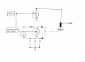
Yes Max and Shortbus, it is indeed a schematic by Mr Langlois, this one being a reprint done in 2007.
The idea to drive the EDM (this one being a plunger-type) is to drive a step motor by taking the inputs from two comparators that in turn are being driven by the voltage present at the spark supply's capacitors. These comparators either move the electrode up, keep it where it is, or move it down, depending on their adjustment. The stepping speed is provided by a good ol' 555, as can be clearly seen from the schematics.
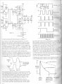
T3, T4 = 30 Vac transformers (42 Vac peak)
R1 = 15Ω @ 240W, R2 to R6 =1M @ 1/2 W
All caps should be rated for 150V
C1 = 2,000 µF, C2 = 50 µF, C3 = 100 µF, C4 = 200 µF, C5 = 400 µF, C6 = 50 µF
BR1, BR2 = 25 Amp @ 200V
The Langlois book was first a series of articles in Home Shop Machinist, then reprinted as the book. Of the RC EDM's it is the best. Took the time to explain why/how to do things. Since you have more understanding of circuits than me, would you look at the one shown page 52, Figure 6.8, if you have time? I and others can't see how it can work, using high side mosfets to switch other high side mosfets?
OK, been doing some more thinking on this pulse EDM and came up with this simplified schematic. Simplified in that there are no part values yet, more of just a flow chart. If it looks "workable" to those with more knowledge, I'll start to flesh it out. Please have a look and comment, thanks.
While it has an inductor, the inductor is really just used as a voltage multiplier, to get the spark started in the gap. Kind of like the old time "low tension spark coil" they used in the old 'hit and miss' gas engines used in the early 1900's. http://en.wikipedia.org/wiki/Low_tension_coil
I'm afraid you're gonna have to ask @MaxHeadRoom or @#12 about that, they have a far better understaning of mosfets than me.
I've attached the page with the figure you've mentioned, as a reference.
Thats one of the problems with Flemming and his two books. With each printing he updates and never posts the update in his forum. I have edition #1, printed in 2005, was one of his first customers, and there been 4 or 5 editions since. Makes it fun when everyone is talking about a different circuit.
Mine shows edition 1997.
It appears to be the same as posted by cmartinez which has quite a detailed explanation of what he is trying to achieve in his later modulator circuit.
Although his circuit in fig 6.8 appears to be a untested one?
I think a better circuit could be built incorporating the later IC's such as the IR2110 Hexfet driver series?
Also a governed means of advancing the electrode has to be fairly precise.
I prefer servo over steppers myself.
Is there any reason of using inductor over capacitors, I would have thought it easier to switch a series capacitors in to vary the erosion?
Max.
I agree. I don't see how the FETs in that circuit would survive if the supply voltage Vf were > ~20V. Their gates would be over-driven, with Vgs ~ the full Vf. Also, according to Spice, most of the current in the workpiece is due to shoot-through in the FETs, rather than discharge from C26/7/8.
I think a better circuit could be built incorporating the later IC's such as the IR2110 Hexfet driver series?
Also a governed means of advancing the electrode has to be fairly precise.
I prefer servo over steppers myself.
Is there any reason of using inductor over capacitors, I would have thought it easier to switch a series capacitors in to vary the erosion?
Max.
The stepper is used in all of the "hole shooter" type EDM's, for small holes to feed the wire through for WEDM. Or at least the ones I've looked at. If you use micro stepping or a slow enough step rate, a stepper is plenty accurate. Mine is driving a 2mm lead ball screw and moves very little per step. Been so long ago, don't remember the actual amount. Flemmings machine/plan uses a Maxon style gear motor, and it 'dithers' back and forth do to it over running the gap.
The reason for the inductor is to get the spark to start every time. Like the Eltee brand I've got an inductor and caps in the circuit. The RC type circuit misses starting many spark cycles, causes problems and makes a slow process even slower.
Yes I was aware there are feedback systems for steppers, but the way I see it is that if you are going with a feedback element then why not go with servo's.
Max.
Yes I was aware there are feedback systems for steppers, but the way I see it is that if you are going with a feedback element then why not go with servo's.
Max.
I've used them before and they have excellent torque. But maybe you're right, especially considering the price of these steppers... maybe for a little more a servo would have better performance.
Yes I was aware there are feedback systems for steppers, but the way I see it is that if you are going with a feedback element then why not go with servo's.
Max.
If your talking industrial type servos here, you must be thinking of building an industrial size machine, correct? In the home/hobby size machine your only moving a pound or less in the ram, why use a full size servo? unless there are some stepper size servos out there. By the time you connect a stepper to a lead screw of some sort 0.001" accuracy is very easy. And since this is not a CNC type machine, personally the servo is way over kill. There is no contact of the electrode with the work, unlike using a cutter with conventional machining.
If your talking industrial type servos here, you must be thinking of building an industrial size machine, correct? In the home/hobby size machine your only moving a pound or less in the ram, why use a full size servo? unless there are some stepper size servos out there. By the time you connect a stepper to a lead screw of some sort 0.001" accuracy is very easy. And since this is not a CNC type machine, personally the servo is way over kill. There is no contact of the electrode with the work, unlike using a cutter with conventional machining.
I've had nightmares in the past using steppers due to missing or extra steps because of EMI or strange spurious signals. When I use steppers I always use feedback positioning sensors. Having said that, yes, a stepper should do just fine for an application like this one.
The window comparator for the gap is what controls the position, regardless of steps. So missed steps are of no consequence. A limit switch is used to control final depth of the 'burn'. Burn is the name used for the operation in EDM, instead of cut.
There is lots of spurious noise in EDMing. An AM radio tuned "off station" near a burning EDM can be heard on the radio. It's a basic old Tesla type spark transmitter.
If your talking industrial type servos here, you must be thinking of building an industrial size machine, correct? In the home/hobby size machine your only moving a pound or less in the ram, why use a full size servo? unless there are some stepper size servos out there. By the time you connect a stepper to a lead screw of some sort 0.001" accuracy is very easy. And since this is not a CNC type machine, personally the servo is way over kill. There is no contact of the electrode with the work, unlike using a cutter with conventional machining.
I guess I am spoiled as I have always used servo's, I tried out steppers at one point and was disappointed in the performance although I agree they appear to be successful used for simple positioning projects and hobby CNC.
But servo's can be as small as you can make a motor, I have some smaller than a typical stepper.
Nowadays with sites like ebay, servo's are just as cheap including the drives.
Although no contact with the work, precise positioning and fast reaction is still a requirement of a successful EDM machine.
Max.
Yeah... but that only works when cutting through a straight line. If you're cutting, say, a round hole, then position monitoring becomes more important.
Yeah... but that only works when cutting through a straight line. If you're cutting, say, a round hole, then position monitoring becomes more important.
Now you have thrown a XY axis into the mix, This usually is a requirement of wire EDM, I would think sinkers are predominantly Z axis move only?
Although the XY would definitely make it more flexible.
Max.
 Facebook
 Google
 GitHub
 Linkedin
")