Facebook
 Google
 GitHub
 Linkedin
Hi,
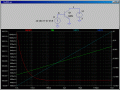
I've recently started to learn a bit about transistors, and I'm currently fiddling around with some test circuits in LTspice. One of them looks like this:
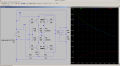
I've removed some wires for testing, so there are some unconnected components (R11 and R12), and there are some low-valued dummy resistors for measuring current. I figured most of the circuit isn't really that important to my question here. Also, the wire is deliberately interrupted at VV. The interesting thing for me here is the PNP transistor Q2, whose currents are plotted as the four resistances in the center are stepped. The emitter and collector currents are measured going into the transistor, the base current is measured going out of the transistor. I can't make sense out of these measurements. They say that current leaves the emitter, but also leaves the base. If they are opposite direction, it can't be an emitter-base-current, can it? Where else does the base current come from? And why does the transistor not open-circuit when there's no emitter-base-current? The magnitude and direction of the base current seems to imply that it comes from the collector, but why does it do that (especially if there's no emitter-base-current)?
What I wanted to achieve here is that when the wire at VV is left open, both Q2 and Q3 go open-circuit too, so that the voltage between the four resistors in the center comes entirely from the upper half of the circuit, cutting off the lower half (it's a simulation of a control circuit for a 4-terminal resistive touch screen).
Any ideas?
I've recently started to learn a bit about transistors, and I'm currently fiddling around with some test circuits in LTspice. One of them looks like this:
I've removed some wires for testing, so there are some unconnected components (R11 and R12), and there are some low-valued dummy resistors for measuring current. I figured most of the circuit isn't really that important to my question here. Also, the wire is deliberately interrupted at VV. The interesting thing for me here is the PNP transistor Q2, whose currents are plotted as the four resistances in the center are stepped. The emitter and collector currents are measured going into the transistor, the base current is measured going out of the transistor. I can't make sense out of these measurements. They say that current leaves the emitter, but also leaves the base. If they are opposite direction, it can't be an emitter-base-current, can it? Where else does the base current come from? And why does the transistor not open-circuit when there's no emitter-base-current? The magnitude and direction of the base current seems to imply that it comes from the collector, but why does it do that (especially if there's no emitter-base-current)?
What I wanted to achieve here is that when the wire at VV is left open, both Q2 and Q3 go open-circuit too, so that the voltage between the four resistors in the center comes entirely from the upper half of the circuit, cutting off the lower half (it's a simulation of a control circuit for a 4-terminal resistive touch screen).
Any ideas?