Making circuit more "sensitive" to changes in resistance

Thread Starter

Jacob Paiste

Joined Jul 30, 2018
6
Hello AAC,

Extremely fortunate I found this forum.

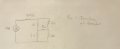
I am working on a project where I need to change the brightness of an LED on a breadboard by changes in the environment. It is sort of a bunch of little projects. One of which where I have a light sensor that depending on the light entering should brighten or dim the LED. The other is the same thing, but with a thermistor. The project consists of using a 9 V DC source, resistors, and wires.

I have been able to get my LED to turn off completely or turn on by using the light sensor. But the thermistor is giving me problems. I believe the problem lies in the varying resistance of these devices.

For the light sensor, when I shine my laser on it the resistance is just shy of 200 ohms. When I cover it up, it goes up to 40,000 ohms. So the LED reacts really nice to these big changes in resistance.

For the thermistor, in room temperature it is around 10500 ohms. When I blow on it, it decreases to 9500 ohms. When I put a lighter next to it the change is weirdly 100-200 ohms at most. These small changes in resistance is not enough for the power of the LED to change enough to make any visible changes with my current configuration. Does anyone have any tips for me to make my circuit more sensitive to small changes in resistance so my LED can react to these changes in temperature?

Kind Regards,

Jacob
 

ericgibbs

Joined Jan 29, 2010
18,766
hi Jacob,
Welcome to AAC.
You need an amplifier circuit, using a transistor is the usual method.
Are you able to get electronic components in your location.?
E
 

WBahn

Joined Mar 31, 2012
29,976
Is this some kind of school project?

Are you only allowed to use the battery, resistors, and wires (in addition to the sensor)?
 

wayneh

Joined Sep 9, 2010
17,496
A comparator would be may choice, eg. LM393. You make your sensor part of a voltage divider and use the comparator to detect mV level changes in voltage due to changes in the resistance.
 

bertus

Joined Apr 5, 2008
22,270
Hello,

Can you post a schematic of the current set-up?
You can upload pictures using the "Upload a File" button, below the reply window.

Bertus
 

WBahn

Joined Mar 31, 2012
29,976
A comparator would be may choice, eg. LM393. You make your sensor part of a voltage divider and use the comparator to detect mV level changes in voltage due to changes in the resistance.
IF he can use additional parts and IF he only needs to make it turn on and off then that is a viable approach. But if he needs it to "brighten" and "dim" as the environmental conditions change, then he needs something different.

@Jacob Paiste : Your first step should be to clearly decide (and articulate) what you want (need, really) and what your constraints are.

This will include getting rid of qualitative words like "brighten" and "dim", beyond using them to give a "big picture" sense of what you are trying to accomplish.

Do you need the LED's brightness to continuously change as the sensor output changes? Or is it acceptable for the LED to be on for all sensor conditions one one side of a threshold and off for all values on the other side?

The next step is to put some numbers to your LED current levels.

The next step is to put some numbers to your sensor resistance values at key points (which you've taken a shot at doing).

The next step is to marry the two together with some kind of a relationship between sensor resistance level and corresponding LED current level. This might be as simple as giving two points at the extreme ends and then seeing if a circuit that comes close to those two operating points is acceptable at other points. If it is, you're done. If not, then you iterate through and pick one or more additional points that you want it to match at.
 

wayneh

Joined Sep 9, 2010
17,496
... if he needs it to "brighten" and "dim" as the environmental conditions change, then he needs something different.
Yup, hadn't thought about a proportional response instead of a 'digital' one. An op-amp instead of a comparator.

But yeah, as usual we need specifications. Care to wager how many posts will it take?
 

WBahn

Joined Mar 31, 2012
29,976
Yup, hadn't thought about a proportional response instead of a 'digital' one. An op-amp instead of a comparator.

But yeah, as usual we need specifications. Care to wager how many posts will it take?
I've learned to not even wager on how many digits are in the number of posts it will take! ;)
 

Thread Starter

Jacob Paiste

Joined Jul 30, 2018
6
Hello

Thank you for all the responses. I came home from work today super pleased to see how many people are willing to help. Thanks!

Here is some more information on the project. I'm a physics major who got tangled in an electrical engineering class. It's been fun, but certainly a learning experience since I had no clue how to even "assemble" a circuit two weeks ago :confused: but could solve a circuit on paper any day. Applying that knowledge has been humbling to say the least!

That being said. The overall project is several small projects:
Light sensor
1. Shine light onto light sensor and have LED brighten.
2. Shine light onto light sensor and have LED dim (or preferably shut off).
Thermistor:
1. Add heat to thermistor, light turns on.
2. Add heat to thermistor, light turns off.

Then I must re do all projects using an amplifier which personally scares the heck out of me. But I think that will be the key to getting the LED to go from bright to OFF or OFF to bright as opposed to just dimming or brightening slightly. I believe that is because the amplifier is made of many transistors which would help? Pardon my ignorance.

I have included a schematic that worked fairly well with the light sensor circuit I designed, but has not been working well with the thermistor circuit. I tried to figure out why and came to the conclusion that it must be due to the fact that the thermistor's resistance does not vary nearly as much as the light sensor's resistance. I suppose an amplifier would solve this problem, but I would like to get the LED to dim and brighten just slightly with environmental change in the sensor using just the sensors, resistors, wire, and 9 V DC source, before I mess with amplifiers.

I hope this information makes it more clear what I am trying to accomplish.

Again, thank you so much for the help. Any tips moving forward from here would be helpful!
 

Attachments

WBahn

Joined Mar 31, 2012
29,976
What are the specs on the thermistor?

When you held a flame near it, my guess is that you didn't have it close enough to change the actual temperature of the core of the thermistor very much. This is probably a good thing as an open flame will probably result in a very narrow range of distances between "has only a little effect" and "permanently damages the thermistor". If you have any flexibility then you might try switching between hot water and cold water (boiling water and ice water, if possible) or perhaps epoxy the thermistor to the surface of an incandescent light bulb or to a power resistor or something else that can get quite hot, but not nearly as hot as a flame.

Your schematic has no LED in it, so how could it work?
 

Thread Starter

Jacob Paiste

Joined Jul 30, 2018
6
What are the specs on the thermistor?

When you held a flame near it, my guess is that you didn't have it close enough to change the actual temperature of the core of the thermistor very much. This is probably a good thing as an open flame will probably result in a very narrow range of distances between "has only a little effect" and "permanently damages the thermistor". If you have any flexibility then you might try switching between hot water and cold water (boiling water and ice water, if possible) or perhaps epoxy the thermistor to the surface of an incandescent light bulb or to a power resistor or something else that can get quite hot, but not nearly as hot as a flame.

Your schematic has no LED in it, so how could it work?

Whoops sorry. LED is between the bottom node and the battery.

I had no clue you could boil these thermistors in water. I'll give that a try. That will definitely introduce larger change in temperature.

I will need to do a demonstration of this though. Boiling water may be difficult, but ice water is definitely possible.

Thanks for the help!
 

WBahn

Joined Mar 31, 2012
29,976
Whoops sorry. LED is between the bottom node and the battery.

I had no clue you could boil these thermistors in water. I'll give that a try. That will definitely introduce larger change in temperature.

I will need to do a demonstration of this though. Boiling water may be difficult, but ice water is definitely possible.

Thanks for the help!
For your demonstration, you might try getting hot water from a bathroom tap or getting hot water from the cafeteria or food court (water for tea/coffee or even dip it in a fresh cup of hot tea/coffee). You may also find that room temperature (water or air) and ice water is enough for your demo.

Make measurements of all three conditions -- ice water, room temperature, and as hot as you will be able to get for your demo -- and let's go from there.
 

Thread Starter

Jacob Paiste

Joined Jul 30, 2018
6
For your demonstration, you might try getting hot water from a bathroom tap or getting hot water from the cafeteria or food court (water for tea/coffee or even dip it in a fresh cup of hot tea/coffee). You may also find that room temperature (water or air) and ice water is enough for your demo.

Make measurements of all three conditions -- ice water, room temperature, and as hot as you will be able to get for your demo -- and let's go from there.
Sounds great.

I really appreciate your help! Thank you!!
 

MrAl

Joined Jun 17, 2014
11,389
Hello there,

LED light output is approximately linear with current. That means if 1ma gives a circuit brightness, then 2ma gives twice that brightness. This also means that the current should be varied according to incidence of light in the room (or wherever you are measuring it) and according to temperature.

Just so you know, thermistors are not that easy to linearize, and you can only get so linear by adding linear components (resistors). Because thermistors are non linear themselves, you can only get three points perfectly correct using resistors and it's not that easy to get that either. Two points would be easier, and then accept whatever comes in between.
To get a nearly perfect linearization, you'd need a microcontroller for example. You could then map the resistance to the light output any way you choose using program code.

The light dependent resistor or photocell is going to be similar, but it does depend on the type of sensor.

In any case you will most likely need a circuit that can deliver the proper current, so you can not use just resistors in most cases. In cases where you can use resistors you have to be able to choose the thermistors (or LDR) to match the application almost perfectly and although that is possible (older analog panel meters for example) it's not something that most people want to do unless they are spitting out hundreds of meters (or other products) a day in a commercial environment.
 

Audioguru

Joined Dec 20, 2007
11,248
Whoops sorry. LED is between the bottom node and the battery.
You make no sense. The battery negative is the bottom node and they are already connected together. Where is the other wire of the LED connected to? Please show it on your schematic instead of using confusing words.
If you connect a 2V LED directly across a 9V battery then it will instantly burn out.
 

Thread Starter

Jacob Paiste

Joined Jul 30, 2018
6
Just so you know, thermistors are not that easy to linearize, and you can only get so linear by adding linear components (resistors). Because thermistors are non linear themselves, you can only get three points perfectly correct using resistors and it's not that easy to get that either. Two points would be easier, and then accept whatever comes in between.
Hello! Thanks for the response!

Could you elaborate on this slightly more for me? What do you mean by getting three points perfectly correct? Pardon my ignorance with electronics :(

Most recently, I've been trying to apply this schematic (photo attached) to my breadboard. RT is the resistance of my thermistor. Which varies from ~8.3 kΩ in room temperature to ~6.5 kΩ when I pinch it. I thought this schematic would be a winner since if I could assemble the resistors in the neighboring branches to the LED to be ~8.3kΩ I don't see any current in that center branch where the LED is. But then when I pinch the thermistor the resistance decreases causing a bias in this set up and allowing current to flow in that center branch. When I did the math it seemed like it would work, but when I apply it, the LED doesn't react to changes in the thermistors resistance.

I am very limited with this project since I can only use resistors, DC source, wires, and the breadboard. I am not even allowed to dip the thermistor in hot or cold water. The point is for me to some how utilize that relatively small change in resistance to get the LED to dim, and then re do the schematic and have the LED brighten due to change in resistance in the thermistor.


Attachments

Thread Starter

Jacob Paiste

Joined Jul 30, 2018
6
You make no sense. The battery negative is the bottom node and they are already connected together. Where is the other wire of the LED connected to? Please show it on your schematic instead of using confusing words.
If you connect a 2V LED directly across a 9V battery then it will instantly burn out.
I am sorry to confuse you. Like I said I am new to this stuff so perhaps being a beginner I come across as "confusing".

None the less, there are plenty of other people here willing to help me so I won't be needing your help.

Good day!
 

MrAl

Joined Jun 17, 2014
11,389
Hello! Thanks for the response!

Could you elaborate on this slightly more for me? What do you mean by getting three points perfectly correct? Pardon my ignorance with electronics :(

Most recently, I've been trying to apply this schematic (photo attached) to my breadboard. RT is the resistance of my thermistor. Which varies from ~8.3 kΩ in room temperature to ~6.5 kΩ when I pinch it. I thought this schematic would be a winner since if I could assemble the resistors in the neighboring branches to the LED to be ~8.3kΩ I don't see any current in that center branch where the LED is. But then when I pinch the thermistor the resistance decreases causing a bias in this set up and allowing current to flow in that center branch. When I did the math it seemed like it would work, but when I apply it, the LED doesn't react to changes in the thermistors resistance.

I am very limited with this project since I can only use resistors, DC source, wires, and the breadboard. I am not even allowed to dip the thermistor in hot or cold water. The point is for me to some how utilize that relatively small change in resistance to get the LED to dim, and then re do the schematic and have the LED brighten due to change in resistance in the thermistor.
Hello again,

By "getting three points perfectly correct" or more easily "getting two points perfectly correct" means that you can get at most two points that match exactly to what you want on the temperature vs resistance curve or temperature vs voltage curve when you use it to create a voltage or even the temperature vs current curve when you use it to create a current or even the temperature vs meter-reading curve when you try to temperature compensate an analog panel meter.
For example, say you want readings as follows:
0 deg C, read 1v
50 deg C, read 2v
100 deg C, read 3v

With a curve that only has two variables you might only get the 1v and 3v readings 'prefect' and have to settle for however the reading for 50 deg C falls into place. It may read 1.9v, or it may read 2.1v for example, which is not perfect.
This happens because there is no control over that third point, and in this case we may want to try calibrating to 10deg C and 90 deg C instead so the reading for 50 deg C falls closer to 'perfect' like 2.05v instead of 2.10v.
To put this another way, thermistors have a natural curve and you can not bend that curve any way you want to. Only two points may come into nearly perfect alignment with the calibration you want.
This is what happens when we add linear components (resistors) to the thermistor. Regular non linear components (like diodes) allow more flexibility, but are much more difficult to apply in the practical setting except for microcontrollers (not really what i call a 'regular' non linear component though) which are easier to apply.

The calibration setup could be as simple as a cardboard box with a light bulb in it for heat generation and temperature meter. As the temperature varies over the range you want you check to see that you are getting the readings you want and adjust components as needed. It's a time consuming process though so you probably want to have other things to do at the same time while the temperature stabilizes at the points you want to test at.

Also, as you try to get the thermistor more linear with components like resistors, you loose measurement resolution. Using a microcontroller improves this a lot too.
 
Top