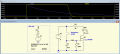
I think using a microswitch with a leaf spring could be mounted so the paddle which moves to strike the bell would close the switch long enough to charge the capacitors in the very simple circuit above. If I get a chance today I'll breadboard it.
Well, my breadboard circuit only worked up to a point. I attached a cardboard paddle to the leaf spring on my microswitch. Using two Li-ion cells in series I attached the switch to the battery and a 6000uf capacitor. I shot a rubber band at the cardboard, the switch closed and I measured over 6 volts on the cap. I was about to pat myself on the back when I remembered that Li-ion cells deliver a LOT more current than AAA cells, so I simulated the AAA cells by inserting a series 20 ohm resistor. Busted! I got only about 0.3 volts.
Still, I think It would be worth it for A20 to test on the real set-up. All it would take is a microswitch and a large capacitor.
Well, my breadboard circuit only worked up to a point. I attached a cardboard paddle to the leaf spring on my microswitch. Using two Li-ion cells in series I attached the switch to the battery and a 6000uf capacitor. I shot a rubber band at the cardboard, the switch closed and I measured over 6 volts on the cap. I was about to pat myself on the back when I remembered that Li-ion cells deliver a LOT more current than AAA cells, so I simulated the AAA cells by inserting a series 20 ohm resistor. Busted! I got only about 0.3 volts.
Still, I think It would be worth it for A20 to test on the real set-up. All it would take is a microswitch and a large capacitor.
I think that 20 Ω is probably too aggressive. That would limit the peak current to something around 300 mA and AA cells (what the TS is using) can output more than that, at for the initial burst.
The Duracell website indicates a cell DC resistance of between 0.1 Ω and 0.3 Ω and their high-drain test is done at 1 A background draw with a 2 A spike lasting for one second every five minutes.
Well, you can briefly touch the battery revered polarity. LEDs are rated for maybe 7V reverse. So, it does good and bad things.
1) Reverse polarity protection when changing batteries. +- is never well marked. How many times do you just rotate until it fits.
2) Considerable voltage drop 0.6 standard diode. Better Shockley diode, Lower drop with FET circuit.
My opinion here, but I think 6000 µF is too big. With 2000 µF I got (in the video) about a 3 second decay. Especially putting a current limiting device in series with a capacitor you want to charge as much as possible. Remember, the capacitor will take what it wants. As it charges the current drops. So even if you had a million amps available the cap is still going to charge at its own rate.
According to the user manual option #12 allows OFF DELAY:
Upon application of input voltage, the time delay relay is ready to accept a trigger. When the trigger is applied, the output is energized. Upon removal of the trigger, the time delay (t) begins. At the end of the time delay (t), the output is de-energized. Any application of the trigger during the time delay will reset the time delay (t) and the output remains energized.
Although, is says 6 - 20 Vdc and i'm not sure if four AA batteries will provide that.
My rig measures 6.3 volts right now. Batteries are new. Two cells measure at 1.57 volts, the other two are at 1.58 volts per cell. The drain from an LED will be very minimal and the nature of the amount of energy you use each time the target is hit is low. Likely your batteries will withstand a month or more of target practice. Wouldn't surprise me to hear that even after 6 months the batteries are still above 1.5 volts.
Running into supply issues. I have 100KΩ for R1 and 22µF for C1 (post #21). My MOSFET (the only one I can find in my stock right now) is a 2SK1277, High Voltage 30 amp MOSFET. Using that in place of the 2N7000 (in post #21), when I run the test I get one second of full brightness of the LED, then the next second it dims to nothing. So I get a 2 second pulse using those values and the circuit posted in #21. I know the sim says using a 4.7µF cap and a 270KΩ resistor will give you a 3 second duration of nearly full brightness, then quickly fade out (less than a half second). Don't know why mine works so differently, likely it's because I'm using this HUGE MOSFET. I know I have a baggie of MOS's somewhere, but for the life of me, sometimes I can't find the keyboard on my computer - that's how messy my lab gets sometimes. When I actually find my MOS's I'll try again and see what the results are. For now, using the devices I've listed I get a 1 second full potential then for the second second I get a steady decay. Take it for what you like. It's also a cheap circuit and just as easy to modify. And I've shortened the length of my contact wire, so when I swipe my hook wire across it - it makes even less contact (time wise) and still gives full brightness for the one second.
[edit] I've replaced R1 with a 220KΩ and get about twice as long (stands to reason, double the resistance of R1 and you double the period {length}). 2 seconds of full brightness followed by a 2 second decay.
Probably. But it would be like using a world war two flame thrower to toast your bread in the morning. A bit of over-kill if you ask me. Yes, it would work. Depending on how fast it responds to a trigger (target switch). If it's slow then the trigger will probably be too fast for it. And I suspect that is going to be the case. I like both circuits you've been shown. The one with the MOSFET (the 2N7000) will probably work better for your purpose than the one I drew earlier. As I mentioned, I'm testing that circuit but not sure why it's taking far longer with MY rig than the sim showing a 3 second pulse duration. But hey! The circuit works. Just modify the time duration by changing either the cap size or the resistance. More capacitance or more resistance and the light will be lit longer. Lower values for shorter duration.
Do you have a bread board? Like the one I have in my video? They're a great way to prototype a circuit and modify it to suit your desires. If you don't have one and are serious about a hobby in electronics then I'd recommend you get one. And don't go cheap. Get a good one and you'll be satisfied with the results. Cheap ones bring unintended problems into your circuits; and can be difficult to troubleshoot.
No. He wants the light to come on for a few seconds. In some circuits the LED lights up then decays in brightness. Using 2000µF an LED will light and decay over about 3 seconds, depending on the current the LED is set to use. The second circuit uses a MOSFET, which I've found the small pack I have of them. IRF3205's. Using 10µF and a 220KΩ resistor to drive the gate voltage of the 3205 I get a light that glows for a second then degrades quite quickly. A lot like the sim on post #21. However, I'm still not getting a 3 second light. I could UP the resistance, but in the sim it's calling for a 4.7µF where I'm using 10µF. Post #21 uses a 240KΩ resistor, I'm using a 220KΩ resistor. Still don't understand why my actual is so different from the sim. Eh! Whatever. ON MY BENCH; 10µF charged from 6.3 volts with a 220KΩ bleed resistor results in one second of bright light then it degrades in about a half second (like the sim).

 Facebook
 Google
 GitHub
 Linkedin