 Facebook
 Google
 GitHub
 Linkedin
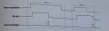
We have a time schedule which looks like this:

Where "Data available" and "Acknowledge" are input signals and "Break" is output signal.
The circuit is going to work in a way so that when "Data available" gives a 1, "Break" should become 1 and then remain 1 until "Acknowledge" gives a 1, then "Break" turns to 0.
I have made a state diagram that looks like this:

However it says that for the state transition diagram, it will not be enough with two states, because of the two cases. But I don't see how the two cases would give different states?
How would you make this diagram, truth table and/or in the end the circuit itself?
Where "Data available" and "Acknowledge" are input signals and "Break" is output signal.
The circuit is going to work in a way so that when "Data available" gives a 1, "Break" should become 1 and then remain 1 until "Acknowledge" gives a 1, then "Break" turns to 0.
I have made a state diagram that looks like this:
However it says that for the state transition diagram, it will not be enough with two states, because of the two cases. But I don't see how the two cases would give different states?
How would you make this diagram, truth table and/or in the end the circuit itself?
Attachments
-
 89.2 KB Views: 70
 -
 43.4 KB Views: 65


