Facebook
 Google
 GitHub
 Linkedin
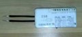
Hi,2. Add a known resistance like 0.1 Ohms
To do this, I will need to find resistors of the corresponding ratings and with minimal inductance.
A large inductance will introduce a large error in the measurement result.
Now I can allow myself to do this - select such maximally suitable resistors, having a very accurate inductance meter.