Make a very simple ESR meter.

Thread Starter

bob2

Joined Jun 15, 2019
224
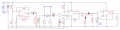
I measured the frequency. Exactly 90 kHz. The voltage at the measuring tips is 75 mV.
With such a low measuring voltage, not a single semiconductor should open. Even the most sensitive Schottky diodes.
It is possible to use a voltmeter.
 

Attachments

Last edited:

MrAl

Joined Jun 17, 2014
11,396
That sounds about right for those component values.
I calculated 88kHz so that is within about 2 percent.

As i said before though, there could be an issue with the bandwidth of the op amps because the slower ones that are commonly used dont have the bandwidth to pass that frequency with any appreciable gain and output swing.
So for example it may work at 90kHz and 1v peak output, but at 2v peak output there probably would be too much distortion.
For any op amp at 90kHz the slew rate has to be at least 0.57 volts per microsecond per peak output volts. So for 2v peak output you'd need twice that slew rate. So the LM358 and similar types probably wont work very well unless distortion is tolerable.
 
Last edited:

Thread Starter

bob2

Joined Jun 15, 2019
224
For any op amp at 90kHz the slew rate has to be at least 0.57 volts per microsecond per peak output volts. So for 2v peak output you'd need twice that slew rate. So the LM358 and similar types probably wont work very well unless distortion is tolerable.
Yes, this is not the best solution. MC 33078 is more suitable.
Here is a similar circuit using LTC6244.
There are two circuits. With and without a transformer.
https://www.eevblog.com/forum/beginners/yet-another-esr-meter-project/
 

Attachments

Last edited:

MrAl

Joined Jun 17, 2014
11,396

MrAl

Joined Jun 17, 2014
11,396
Yeah just mentioning the 100kHz cause that is the more typical.
Does that opamp have the required bandwith and slew rate?
 

MrAl

Joined Jun 17, 2014
11,396
Hello again,

It looks like the device may work up to around 2v peak output at 100kHz. Maybe a little higher but this should still be tested for distortion at 100kHz.
 

MrAl

Joined Jun 17, 2014
11,396
At a frequency of 60 kHz it works without problems. Most likely it will work at a higher frequency.
As for distortions, it is difficult to say about their level in a real circuit and how they will affect the measurement results.
https://files.elv.com/Assets/Produkte/4/477/47773/Downloads/52699_ESR1_UM.pdf
Hi,

If it is difficult then stick close to theory.
min slew rate = 2*pi*f*A
where A is peak output voltage,

The pic shows a slew rate (blue) that is too slow. The red plot is the signal, and everything red above the blue line can not be reproduced properly only the red plot that is under the blue line can be reproduced properly.

We have another issue here though. The oscillator is a square wave. That means we have to consider harmonics like the 3rd, 5th, 7th, etc. Now the lucky thing is that the amplitude for the 3rd is 1/3 of the fundamental, so we might get lucky because that would mean that if the amplifier could pass the required frequency at 1v peak output (for example) then it can pass the 3rd too because it will be 1/3 down from the 1st and if we look at the min slew rate formula we find that if the frequency goes up by 3 times but the amplitude comes down by 1/3 then it can still be passed, theoretically. What might be harder to figure out is the phase shift for the upper harmonics. The margin It would be close though, so some really good testing is advised. Probably with a scope at least.
 

Attachments

Last edited:

Thread Starter

bob2

Joined Jun 15, 2019
224
It is difficult to say how harmonics will affect the final measurement result.
I have not yet found good information on this subject, backed up by practical results.
For me, the main thing is that the oscillator works stably. That's why I used good electronic components.
And the output test signal is close to sinusoidal.
It already depends on the characteristics of the transformer used.
This is another reason why I decided to use a transformer.
Here is what I saw.
https://passive-components.eu/a-simple-method-for-a-capacitors-esr-measurement/
https://meettechniek.info/passive/capacitance.html
https://www.nutsvolts.com/questions-and-answers/capacitor-esr-tester
 
Last edited:

Alec_t

Joined Sep 17, 2013
14,280
It is difficult to say how harmonics will affect the final measurement result.
I don't think you need to worry about harmonics, given the simple circuit and that in general you want only an indication of whether a cap is likely good or bad, rather than a precise measure of ESR.
 

Thread Starter

bob2

Joined Jun 15, 2019
224
I don't think you need to worry about harmonics,
a precise measure of ESR.
I don’t worry about harmonics, so I never talked about them.
And I do not care about a very accurate ESR measurement either.
By the way, what accuracy is needed to measure ESR?
 

Alec_t

Joined Sep 17, 2013
14,280
what accuracy is needed to measure ESR?
Depends on why you are measuring it. If it were me, I'd be happy with 20-30% error if it were just a matter of deciding on whether or not to replace a cap suspected of having too high an ESR. But how will you know what accuracy your built circuit actually has?
 

MrAl

Joined Jun 17, 2014
11,396
Hello,

For some circuits it is good to know the ESR say within 20 percent plus or minus.
I have used the second link method for years and did a complete article on it i'll see if i can find it. Ok i posted it here. Notice you can not rely on the value of the capacitor either if it is older because not only the ESR changes but so does the capacitance.
Note how straight up and down the vertical part of each waveform is. That's because the ESR has no storage capability so the ESR responds immediately to the excitation.

But how do you assume you are getting a sine wave?
 

Attachments

Last edited:

Thread Starter

bob2

Joined Jun 15, 2019
224
If it were me, I'd be happy with 20-30% error if it were just a matter of deciding on whether or not to replace a cap suspected of having too high an ESR.
Well, with the situation, good-bad capacitor, everything is clear.
But what to do in such cases?
1.Check the ESR of the capacitor for compliance with the datasheet.
2. The choice of new capacitors from different manufacturers for a minimum ESR.
3. The choice of the best capacitors from those that were in operation.
4.Determination of ESR values, close to the maximum allowable values.
 

MrAl

Joined Jun 17, 2014
11,396
Hi,

I would look for something close to the spec on the data sheet.

But i noticed the oscillator in post 44 does not look good or else it is drawn wrong.
There is no resistor to the positive supply.
 

Thread Starter

bob2

Joined Jun 15, 2019
224
But how will you know what accuracy your built circuit actually has?
Hi,
Given the fact that the conditions are fairly close, I want to compare the measurement results with the LCR Pro1 Plus.
Here is what we already have.
ESR range-0.02-20 Ohm.
Frequency -90kHz.
Test voltage-75mV.
Test signal is close to a sine wave.
 
Last edited:

MrAl

Joined Jun 17, 2014
11,396
Hi,
Given the fact that the conditions are fairly close, I want to compare the measurement results with the LCR Pro1 Plus.
Here is what we already have.
ESR range-0.02-20 Ohm.
Frequency -90kHz.
Test voltage-75mV.
Test signal is close to a sine wave.
That sounds good.

You can also do this...
1. Measure a caps ESR, call it R1
2. Add a known resistance like 0.1 Ohms in series with the cap call it R2
3. Measure ESR again, the ESR should now read ESR=R1+R2

You can test with R2=0.01, 0.1, 1, and 10 Ohms.
 
Top