Make 12v relays into a AND logic gate

Thread Starter

Colton4612

Joined Aug 25, 2018
8
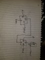
I'm trying to figure at how to wire relays to make a AND gate. I have 2 12v dc inputs and would need to make a AND logic gate that outputs 12v dc. What relays do I need and how would I wire them? Thanks
 

ArakelTheDragon

Joined Nov 18, 2016
1,362
Is requirement to use only relays?

You need to read a little about the standard functions of relays, before you begin this, there are already programmer mistakes, which we are discussing in another thread.
 

Thread Starter

Colton4612

Joined Aug 25, 2018
8
Is requirement to use only relays?

You need to read a little about the standard functions of relays, before you begin this, there are already programmer mistakes, which we are discussing in another thread.
Doesn't have to be relays if there is another option. I just need to figure out how to make a AND gate that outputs 12v DC.
 

KJ6EAD

Joined Apr 30, 2011
1,581
There's more than one way to do it. This is the most common.

You can use any 12V SPDT relays. If you're in a hurry, automotive cube relays are readily available. Some such as the one pictured have the needed suppression diode built in. The terminals accept 0.250" female quick disconnects or can be mounted on a socket base.
 

-live wire-

Joined Dec 22, 2017
959
There's more than one way to do it. This is the most common.

You can use any 12V SPDT relays. If you're in a hurry, automotive cube relays are readily available. Some such as the one pictured have the needed suppression diode built in. The terminals accept 0.250" female quick disconnects or can be mounted on a socket base.
It seems like a waste of money to use high current relays for simple logic level stuff. Getting a small transistor and resistor kit makes a lot more sense. Then just use an and gate like this.

https://www.amazon.com/Transistor-2...qid=1535424457&sr=8-4&keywords=transistor+kit
https://www.amazon.com/Cutequeen-75...8&qid=1535424439&sr=8-3&keywords=resistor+kit
 

KJ6EAD

Joined Apr 30, 2011
1,581
Last edited:

rsjsouza

Joined Apr 21, 2014
383
It seems like a waste of money to use high current relays for simple logic level stuff. Getting a small transistor and resistor kit makes a lot more sense. Then just use an and gate like this.

https://www.amazon.com/Transistor-2...qid=1535424457&sr=8-4&keywords=transistor+kit
https://www.amazon.com/Cutequeen-75...8&qid=1535424439&sr=8-3&keywords=resistor+kit
live wire, despite I agree with you 100% on the unnecessary complexity of the circuit, the proposed diagram only works with MOS transistors - as soon as a voltage is present on the "B" input, the Base-Emitter diode is forward biased and therefore a small voltage is present on the output pin. The ideal scenario would be to use a NAND and then invert its output.
 

Attachments

-live wire-

Joined Dec 22, 2017
959
Relays work fine for what I needed and only cost me $15 for 5 of them.
Or you can spend 7 dollars on transistors and get 200, and if you get a few resistors, you can make tens of gates. For the same price. You can also get a ton of logic gates for about the same price. They often include many gates in one chip.

30 Types 74HC Series Logic IC Assortment Kit, High-Speed Si-Gate CMOS IC In Assortment Box https://www.amazon.com/dp/B01HECF42U/ref=cm_sw_r_cp_api_Y9wHBbTNV2RNT

As a beginner, I also wanted to use relays for everything. They can be more intuitive. But they have their disadvantages, and sometimes it just doesn’t make any sense, like here. You need to learn how to use transistors and ICs.
 
Last edited:
Top