Magnetically coupled circuit analysis

Thread Starter

bizuputyi

Joined Aug 3, 2014
21
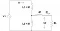
Given circuit shows an ideal autotransformer (k=1 and no power losses).

(a) Apply Kirchhoff’s laws to write down two equations to express the voltages V1 and V2 in terms of the self and mutual voltages induced across the two coils.

(b) Hence obtain an expression for the voltage ratio \( \frac{V_1}{V_2} \) for the condition
L1 = 4L2.

(c) Determine the supply voltage and current with a 10 Ω load carrying
100 A and L1 = 4L2.

Question (a):

KVL loop 1:

\( V_1=j\omega L_1I_1+j\omega L_2I_1-j\omega L_2I_2+j\omega MI_2-j\omega MI_1 \)

KVL loop 2:

\( V_2=-j\omega L_2I_2+j\omega L_2I_1+j\omega MI_1 \)

Question (b):

if \( L_1=4L_2 \)
then \( M=k\sqrt{L_1L_1}=1\sqrt{4L_2L_2}=2L_2\)

so \( V_1=j\omega 3L_2I_1+j\omega L_2I_2 \)
and \( V_2=j\omega 3L_2I_1-j\omega L_2I_2 \)

\( \frac{V_1}{V_2}=\frac{j\omega 3L_2I_1+j\omega L_2I_2}{j\omega 3L_2I_1-j\omega L_2I_2}\)

Is that correct? And what's next from here?

Question (c):

\( V_2=1000V\)

That's all I've got on this.
Your help is greatly appreciated.
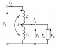
 

Attachments

t_n_k

Joined Mar 6, 2009
5,455
A rigorous solution requires some careful thinking:

Referring to the schematic attachment ....

The current in the L2 winding branch [call it I3] is given by

\(I_3=\frac{V_2-j\omega M I_1}{j\omega L_2}\)

The current I1 in the L1 winding branch is given by

\(I_1=\frac{V_1-V_2-j \omega M I_3}{j \omega L_1}\)

Solving these two equations by elimination of either I1 or I3 then leads to the elimination of the other by virtue of the appearance of the multiplier term

\(\frac{M^2-L_1L_2}{L_2M}\)

This term equates to zero for perfect coupling between L1 & L2.

Hence both current terms vanish in the simultaneous solution and from there one determines that

\(\frac{V_2}{V_1}=\frac{L_2}{L_2+M}\)

or

\(\frac{V_1}{V_2}=\frac{L_2+M}{L_2}\)
 
Last edited:

MrAl

Joined Jun 17, 2014
11,487
Hi,

Just a quick note here, because k=1 we have a case of perfectly coupled inductors which make a perfect transformer, so we have the voltage transfer formula (or here the "voltage divider formula") of the simple:

Vout=Vin*sqrt(L2)/(sqrt(L1)+sqrt(L2))

where
Vin is the input voltage, Vout is the output voltage, L1 is the 'upper' inductor, L2 is the 'lower' inductor, and the output Vout is taken across L2 and Vin is applied across L1 and L2 in series.

Note the similarity to the resistive voltage divider formula, except here instead of using R we use sqrt(L).

In the case where we know L1=K*L2 (upper case K a different constant) we have solution:
Vout=Vin*1/(sqrt(K)+1)

so for L1=4*L2 we get:
Vout=Vin*1/3=Vin/3
 
Last edited:

The Electrician

Joined Oct 9, 2007
2,970
Question (a):

KVL loop 1:

\( V_1=j\omega L_1I_1+j\omega L_2I_1-j\omega L_2I_2+j\omega MI_2-j\omega MI_1 \)

KVL loop 2:

\( V_2=-j\omega L_2I_2+j\omega L_2I_1+j\omega MI_1 \)
Your KVL equations are incorrect; you should have:

KVL loop 1:

\( V_1=j\omega L_1I_1+j\omega L_2I_1+2j\omega MI_1 -j\omega L_2I_2-j\omega MI_2 \)

KVL loop 2:

\( 0=-j\omega L_2I_1-j\omega MI_1+j\omega L_2I_2+R_L I_2 \)

The term with the factor 2 in the first equation can be a bit tricky. The mutual inductance couples from L2 to L1 and then also from L1 to L2.

You shouldn't have V2 as the left side of your second equation. V2 is not a voltage source in the second loop. Don't be fooled by the fact that the voltage drop across RL is labeled V2; that doesn't make it a voltage source. V2 will be given by I2*RL.

Now, with the correct equations, see if you can get better results.
 

Thread Starter

bizuputyi

Joined Aug 3, 2014
21
Thank you everyone for your reply.

This is brilliant, I mean I didn't think there were three different methods to get the solution. I get all of them. Thank you!
 

t_n_k

Joined Mar 6, 2009
5,455
One can also make use of the alternative equivalent circuit shown in the attachment. The mutual inductance is included in such a way as to enable one to treat the inductances as three uncoupled elements. The negative element (-M) is a bit of a mental hurdle but the analytical outcome is the same.

Using this schematic and applying the voltage divider rule based on component values it's possible to show after some manipulation (and provided there is unity coupling) that ...

\(\frac{V_2}{V_1}=\frac{\( L_2+M \) \( R_{\small{L}} - j\omega M \)}{\(L_1+ L_2 + 2M \) \( R_{\small{L}} - j\omega M \)}=\frac{\( L_2+M \)}{\(L_1+ L_2 + 2M \)}\)

Hence given L1=4*L2 with unity coupling (k=1) we obtain ...

\(M=2L_2\)

and

\(\frac{V_2}{V_1}=\frac{\( L_2+M \)}{\(L_1+ L_2 + 2M \)}=\frac{3L_2}{9L_2}=\frac{1}{3}\)
 

Attachments

Last edited:

Thread Starter

bizuputyi

Joined Aug 3, 2014
21
That's impressive. I'm getting the idea how I should think, however I'm not yet confident enough to always find the correct signs when dealing with M or applying KVL (with M), definitely need more practice to gain that confidence.
The way you put this exercise it looks fairly easy to solve.
Thank you for your effort.
 
Top