 Facebook
 Google
 GitHub
 Linkedin
Hi everyone please help me out with this question, If the question is not clear in the picture:
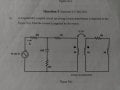
a) A magnetically coupled circuit involving a linear transformer is depicted in the Figure3(a). Find the current Io Supplied by the source.
a) A magnetically coupled circuit involving a linear transformer is depicted in the Figure3(a). Find the current Io Supplied by the source.
Attachments
-
 101.4 KB Views: 28


