LTS Modeling of Capacitor Transient Current Charging and Discharging

BTW I believe the schematic in post #40 shows voltage across the capacitor. To measure the voltage across the capacitor, resistor, we have to rearrange the order of components. Correct me please if I am wrongddddd.JPG
 

Thread Starter

SamR

Joined Mar 19, 2019
5,526
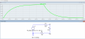
Let's start here... Added a 1ms delay and plotting the voltage across C1
1773192878857.png
So far, so good. But, there is already a 4V partial charge on C1.
So I add .ic v(Vout)=4 so that when C1 starts charging there is already 4V across it? I'm not sure that I am interpreting this statement correctly? Or if it is actually what I am wanting to use here?
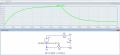
But I then get
1773192509668.png
And now the input voltage starts at -4V so, no, that's not correct. Just how can I put or is it even possible to put a partial charge of 4V on C1??? Just how is this .ic statement parsed? Need to find the documentation for this statement as I don't understand what it is saying to do...
 

Thread Starter

SamR

Joined Mar 19, 2019
5,526
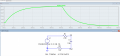
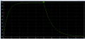
OK, got it! Now it starts @ an initial 4V across C1! And drops to 0V when C1 fully discharged.
1773193696860.png

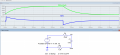
And the current looks correct as well.
1773194252713.png
I think I can mark this one done! Thanks for the help folks!
 
Last edited:

Thread Starter

SamR

Joined Mar 19, 2019
5,526
A couple of follow up comments. The concept of switching the PSU instead of a mechanical switch was something I had not considered but is a far better approach to the problem. Also @crutschow the idea of putting in a diode instead of a mechanical switch is a novel approach and works great for the discharge phase. But when I started thinking about the concept in that circuit, I realized it causes a voltage divider to be introduced into the charging phase and skews the charging curve accordingly. But I like the idea!
 

crutschow

Joined Mar 14, 2008
38,689
the idea of putting in a diode instead of a mechanical switch is a novel approach and works great for the discharge phase. But when I started thinking about the concept in that circuit, I realized it causes a voltage divider to be introduced into the charging phase and skews the charging curve accordingly.
How so?
See sim below:
During the charge, the voltage across R1 (green trace), is the input voltage minus the small diode forward-voltage drop (which is compensated by having the input volage be 10.6V).
Note that the capacitor charge and discharge times are essentially the same as the sim with the switch.

1773242469000.png
 
Last edited:

Thread Starter

SamR

Joined Mar 19, 2019
5,526
?
Note that the capacitor charge and discharge times are essentially the same
Are they? Looking at the curve I see ~8.3V charged in the first second of the charging phase and ~6.3V discharged in the first second of the discharging phase? I'm missing something here... Shouldn't that be...
1773243459752.png
No! I see it now, the period τ has changed in the discharge phase due to the addition of the R1 resistor to ground! OK, I misinterpreted the graph. But ONLY R2 is involved in the charging of the capacitor. I played a bit with the circuit in LTS and what appeared to me as a voltage divider is NOT. Both resistors go to ground and they do affect the charge and discharge rates, but the voltage on the capacitor is always the same! OK, I have it now, Thanks!
 

WBahn

Joined Mar 31, 2012
33,076
?

Are they? Looking at the curve I see ~8.3V charged in the first second of the charging phase and ~6.3V discharged in the first second of the discharging phase? I'm missing something here... Shouldn't that be...
View attachment 364543
No! I see it now, the period τ has changed in the discharge phase due to the addition of the R1 resistor to ground! OK, I misinterpreted the graph. But ONLY R2 is involved in the charging of the capacitor. I played a bit with the circuit in LTS and what appeared to me as a voltage divider is NOT. Both resistors go to ground and they do affect the charge and discharge rates, but the voltage on the capacitor is always the same! OK, I have it now, Thanks!
That's not because of any voltage divider action.

The cap is charging through a single 5 kΩ resistor and discharging through both 5 kΩ resistors in series. The diode isn't changing that, it's the same situation as the circuit it is replacing.

Also, note that if you want simulations that match your hand calculations very closely, as opposed to ones that are more reflective of the real-world behavior, you can use ideal models for devices. That allows you to have diodes that have zero voltage drop when on (or a fixed voltage drop that doesn't change with current), and transistors that have fixed, Vbe and ß.
 

Thread Starter

SamR

Joined Mar 19, 2019
5,526
if you want simulations that match your hand calculations very closely
I understand that real models require actual measured values, but these close approximations are all that I'm looking for here. Much easier to let the software draw the curves than doing all the calculations and plotting the results!

That's not because of any voltage divider action.
My brain was playing tricks on me. It's not even a series divider circuit but a simple parallel one with the voltage across both resistors.
 
Top