LTS Modeling of Capacitor Transient Current Charging and Discharging

Thread Starter

SamR

Joined Mar 19, 2019
5,526
Have you included that 'startup ' in the duplicated .TRAN 10 startup setting for the simulation?
E
I did at first, but when it discharged it kept the capacitor @ 4V instead of discharged the complete 24V it was charged to. So, I took it off to see the "actual" discharge curve and forgot to put it back on. But yes, I did have it on when looking at the charging curve with an initial charge of 4V on C1.

I already have the LTSIV paper, but not the LTSpiceIntro so I'll peruse it later. Sadly Analog.com has very little other than 4 short demo videos.

Took me a while to figure out just where LTS was storing my files but...
 

Attachments

Last edited:

eetech00

Joined Jun 8, 2013
4,724
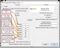
I've got an issue with the lack of documentation for LTSpice parameters. There have been many books and articles written on using/application of LTS for various types of circuits, but I don't seem to find anything documenting the definitions of the actual parameters used in LTS. For example, PULSE(V1 V2 Tdelay Trise Tfall Ton Period Ncycles). Where are these parameters defined in the documentation? Some of it I can suss out from the entry fields and how they were used in the example @WBahn gave but where is it defined?
Hi
You are correct that LTspice doesn't have the best documentation. That opinion is shared by many LTspice users.
But to ADI's credit, they have begun improve the documentation.

One thing that helps is knowing what to look for. Since LTspice is a "spice" based tool, it helps to know a little about spice devices (circuit elements) and their names. The PULSE generator you are using is called an "Independent Voltage Source", or "Voltage Source" for short, and its default designator prefix is "V". Now, knowing what we are looking for, we can now look it up in LTspice help.

1. Click on help, then click LTspice help to launch the Help page.
2. Below "Contents", expand "LTspice Simulator", then expand "Circuit Elements".

The devices will be listed in "device prefix order", so scroll down until you locate "V. Voltage Source".
Click in the left page and scroll down until you find "Time-Dependent Pulsed Voltage Source". Below this section there is a description the device and it parameters.

The actions I've described above is typical for finding information using "Help".

So now all you need do is configure the desired "pulse" using the device parameters. So it helps to know the attributes of a Pulse waveform. You can find this information using your "inner google" or using google internet search.

BTW-
1. It helps to specify a delay in the pulse source so you can clearly see when charging begins, and remember to extend the simulation time by the same amount.
2. When you want to look at the voltage across the capacitor, click+hold the net name at one end of cap, then release click over the net name at the other end of cap. The trace should display both net names as as a trace labeled V(Vin,Vout) in the waveform viewer.
.
 
That's a stupid One Drive issue. I hate One Drive (which is not to say that it doesn't have it's uses). I don't mind the concept of having a cloud drive that I can use, but I hate Windows always trying to force me into using it. I used to have to disable it every couple of months. I haven't had to do that for some time, so perhaps enough people complained?


This is one of the main reasons I don't upgrade until I have to -- I get real tired of having to relearn how to do even simple things.
I had the same agony, troubleshooting software that seemed fine, but did not work, and worst of all, no error to tell what the heck is the wrong. It always ended up the software using the OneDrive path for one of its functions. Luckily, Copilot showed me the trick to bypass this issue. I have never run into such problems ever since.
 

eetech00

Joined Jun 8, 2013
4,724
I had the same agony, troubleshooting software that seemed fine, but did not work, and worst of all, no error to tell what the heck is the wrong. It always ended up the software using the OneDrive path for one of its functions. Luckily, Copilot showed me the trick to bypass this issue. I have never run into such problems ever since.
I hate when MS does that. The first time I saw the "one drive" icon in my task bar, I immediately disabled/removed it.
I recommend re-checking for "one drive" every time a MS update occurs.
 
One key fact that was not addressed in the answers is that the real world components are significantly different than the LTS default models. The curve of a ceramic cap is different than that of an electrolyte cap. I mention this because I have seen successful YT content creators with many subscribers who use wrong pick of capacitor in a circuitry
 
I hate when MS does that. The first time I saw the "one drive" icon in my task bar, I immediately disabled/removed it.
I recommend re-checking for "one drive" every time a MS update occurs.
The trick is bloating your OneDrive with files that you do not even want to back them up! We do not know how many people feel forced to buy bigger and bigger OneDrive storage and how much money MS makes from this trick under the pretext of "protecting your device from ransomware" blahblah
 

eetech00

Joined Jun 8, 2013
4,724
One key fact that was not addressed in the answers is that the real world components are significantly different than the LTS default models. The curve of a ceramic cap is different than that of an electrolyte cap. I mention this because I have seen successful YT content creators with many subscribers who use wrong pick of capacitor in a circuitry
Electrolytic caps are not native to LTspice (or spice for that matter). If you want that behavior, you'll need to model one.
I wouldn't trust the majority of any YT LTspice videos, other than from ADI. Most YT vids are wrong.
 
Electrolytic caps are not native to LTspice (or spice for that matter). If you want that behavior, you'll need to model one.
I wouldn't trust the majority of any YT LTspice videos, other than from ADI. Most YT vids are wrong.
Those videos were not using simulators. They breadboaded them and used real oscilloscope to check the waveform.
 

WBahn

Joined Mar 31, 2012
33,076
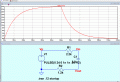
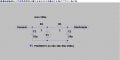
Spent some time going over the results here and familiarizing myself a bit with the new version. Going to simulate an example from Boylestad. I like the simplicity of eliminating the switch and diode additions to the circuit that @WBahn presented so I'm going to start there. I've got an issue with the lack of documentation for LTSpice parameters. There have been many books and articles written on using/application of LTS for various types of circuits, but I don't seem to find anything documenting the definitions of the actual parameters used in LTS. For example, PULSE(V1 V2 Tdelay Trise Tfall Ton Period Ncycles). Where are these parameters defined in the documentation? Some of it I can suss out from the entry fields and how they were used in the example @WBahn gave but where is it defined? Anyway... Here is the problem to analyze in LTS.
View attachment 364477For which τ=11.2ms x5≅60ms .: for Ton= 0.06 Here is where I'm a bit lost. I have no clue as to just what Tperiods definition is but assume from the above example it should be 2xTon so Tperiods=.12
View attachment 364490
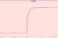
For which when I run the analysis...
View attachment 364491
Hmmm... The Vin does not start @ 4V? I thought it might be the .ic v(Vout)=4 but removing it still gives...
View attachment 364493
So, I'm a bit confused... Good place to take a break...
Note that your Vout is NOT the voltage across the capacitor, it is the voltage across R2.

The voltage AT (or ON) a node is implicitly the voltage difference between that node and whichever node is defined as Node 0 (which you do by placing the Ground symbol on it, which is why the simulation won't run unless you do this).

So our I(C1) curve will be directly proportional to your V(vout) curve, which it is. It may not look that way at first glance because they are inverted relative to each other, which just means that the proportionality constant is negative). The explanation for this is that why you ask SPICE for the current through a two-terminal device, such as a resistor or capacitor, what it returns is the current INTO whichever pin is declared first (Pin 1).

By setting an initial condition of Vout to be 4 V, that merely forces the initial current in R2 (and, since they are in series, in C1) to be 4 V / 1.2 kΩ = 3.33 mA. What it does not do is require any particular voltage on the capacitor. But it does force that same 3.33 mA to flow through R1, which makes the initial voltage at Vin equal to V1 - (3.33 mA)·(2.2 kΩ). With V1 starting at 0 V (it turns on at t = 0 s, but the DC operating point is determined based on the assumed conditions just before t = 0), that -7.33 V. I can't tell if that matches your simulation because the trace of Vin at t=0 is overlaid by the other traces. But assuming this is correct, that places the initial voltage on the capacitor at

Vc = Vin - Vout = -7.33 V - 4 V = -11.33 V.

When V1 then steps up to 24 V, that would put a total of 35.33 V across the series combination of R1 and R2, resulting in a current of around 10.4 mA (which might be depicted as -10.4 mA on the plot). That's in rough agreement with your plot, though your magnitude seems a bit less than that.

You want to learn how to dictate the axis scaling and labeling of your plots. Also, putting traces in different plots or adding offsets to them can help.
 

WBahn

Joined Mar 31, 2012
33,076
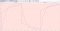
Here is the difference between caps of same capacitance but different built
And how is anyone looking at that plot supposed to know which trace goes with which cap?

I don't understand why people will not label the nodes that they want to display on a plot. Instead, they seem to think that it is somehow intuitively obvious to strangers on the Internet which node is n002, n005, and n006.

Also, please keep in mind that the TS is not asking about, or concerned with, the differences between different physical capacitors. They are exploring and trying to understand the basic behavior of ideal components and how to set up simulations to do so.
 
And how is anyone looking at that plot supposed to know which trace goes with which cap?

I don't understand why people will not label the nodes that they want to display on a plot. Instead, they seem to think that it is somehow intuitively obvious to strangers on the Internet which node is n002, n005, and n006.

Also, please keep in mind that the TS is not asking about, or concerned with, the differences between different physical capacitors. They are exploring and trying to understand the basic behavior of ideal components and how to set up simulations to do so.
Because the posts imply that the TS is familiar with the app environment and I attached the spice file so anyone can simulate it. I do not know whether the older versions of LTS have the components or not, but I am pretty sure any LTS can load .asc and sim it.
 

WBahn

Joined Mar 31, 2012
33,076
Because the posts imply that the TS is familiar with the app environment and I attached the spice file so anyone can simulate it. I do not know whether the older versions of LTS have the components or not, but I am pretty sure any LTS can load .asc and sim it.
And the only way that they can determine which node is associated with which trace is to open the netlist file and reverse engineer it.

What is SO HARD about labeling the nodes that you are displaying?
 
Top