 Facebook
 Google
 GitHub
 Linkedin
Go HERE to see where this project started or I could also say stalled.
Thanks to DickCappels and AnalogKid for the direction they gave me in my final product.
So not to bore you all with the non-electrical part of the project I will only be including the core images of this project. In other words, the BRAINS of the project.

This was by far the most challenging part of the project for a NEWBIE such as myself.. But, it is what gives this clock its Bling! This feature sets this clock apart from all the other Shotgun Shell clocks on the Internet. None of which I found on Instructables. This might be the only Shotgun Clock in this community.
When I first thought about this project, I thought I would be able to find a light sensor module somewhere online (Ebay or Amazon) that I could easily throw into this project and I would be done. I was wrong. I just do not think they exist.
The closest I came was a 12 volt light sensor relay switch. While it would work, the 12 volt battery pack you need to power it posed a problem. There was not enough room inside the box to house a clock mechanism, relay switch, and battery pack. (8 AA batteries). Now this might be an option for you if your design will be a larger box.
Problem Solution
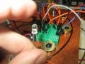
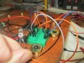
First let me say this is MY FIRST circuit built with any components other than wires and manufactured circuit boards. I had to actually build this from scratch. I amazed myself when it worked.
See the diagram above. I redrew this based on a pencil sketch that I found here on Instructables. The first challenge was to read and follow the schematic. Next was having the parts. Then getting it to work.
Parts
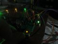
NOTE: By modifying the resistor to dim the LEDs this also made the sensor LESS sensitive which was a good thing. With the 100k resistor simply waving your hand over the sensor would trigger the circuit. Now with the 470K resistor, you need a nearly dark room to trigger circuit.
After 2 weeks the 9 volt battery is powering just fine. With daylight the LEDs are off, and as the room becomes darker the LEDs become brighter.


I am really happy with the final result.
I am really happy that I persevered with the challenge of the Light Sensor Circuit. I might take it a step forward and have a few made by one of these online fab shops just to have a few on hand.
If anyone has any advice on how to get some PCBs made with the cicuit included in this project please let me know.
And of course if you see in possible improvements, please advise.
Thanks and keep Making!
DIYWaterDog
Thanks to DickCappels and AnalogKid for the direction they gave me in my final product.
So not to bore you all with the non-electrical part of the project I will only be including the core images of this project. In other words, the BRAINS of the project.
This was by far the most challenging part of the project for a NEWBIE such as myself.. But, it is what gives this clock its Bling! This feature sets this clock apart from all the other Shotgun Shell clocks on the Internet. None of which I found on Instructables. This might be the only Shotgun Clock in this community.
When I first thought about this project, I thought I would be able to find a light sensor module somewhere online (Ebay or Amazon) that I could easily throw into this project and I would be done. I was wrong. I just do not think they exist.
The closest I came was a 12 volt light sensor relay switch. While it would work, the 12 volt battery pack you need to power it posed a problem. There was not enough room inside the box to house a clock mechanism, relay switch, and battery pack. (8 AA batteries). Now this might be an option for you if your design will be a larger box.
Problem Solution
First let me say this is MY FIRST circuit built with any components other than wires and manufactured circuit boards. I had to actually build this from scratch. I amazed myself when it worked.
See the diagram above. I redrew this based on a pencil sketch that I found here on Instructables. The first challenge was to read and follow the schematic. Next was having the parts. Then getting it to work.
Parts
- Breadboard
- Light Sensor Transistor
- NPN Transistor
- Resistor
- Jumper Wires
NOTE: By modifying the resistor to dim the LEDs this also made the sensor LESS sensitive which was a good thing. With the 100k resistor simply waving your hand over the sensor would trigger the circuit. Now with the 470K resistor, you need a nearly dark room to trigger circuit.
After 2 weeks the 9 volt battery is powering just fine. With daylight the LEDs are off, and as the room becomes darker the LEDs become brighter.
I am really happy with the final result.
I am really happy that I persevered with the challenge of the Light Sensor Circuit. I might take it a step forward and have a few made by one of these online fab shops just to have a few on hand.
If anyone has any advice on how to get some PCBs made with the cicuit included in this project please let me know.
And of course if you see in possible improvements, please advise.
Thanks and keep Making!
DIYWaterDog
Attachments
-
 162.7 KB Views: 10
 -
 174.3 KB Views: 7
 -
 183.8 KB Views: 7
 -
 112.6 KB Views: 8
")


