Low tech: a hamster power plant

mjhilger

Joined Feb 28, 2011
118
I like the magnets on the wheel idea. That could generate the most efficient setup and let you decide on the windings. My daughter several years ago got a magnet building set that has several plastic coated magnets about 1" long x 1/8" round. You could attach those to the wheel.
On the con side, the wheel would then have quite an inertial moment. Bill alluded to it earlier about the hamster @ 100 degrees, but with the moment of the added weight when he tried to stop, he might make several trips around before he could get out!
 

wayneh

Joined Sep 9, 2010
18,152
My daughter several years ago got a magnet building set that has several plastic coated magnets about 1" long x 1/8" round.
A more perfect magnet would be neodymium (very strong field) and be shaped wide and flat instead of long and thin. The oomph generated in the coil as the magnet passes by will be proportional to the field strength and the area of the face of the magnet, and the number of loops of copper wire. I think the right magnets might add only a little inertia, which is a valid concern.
 

Kermit2

Joined Feb 5, 2010
4,159
Winding and positioning the coils will try the patience of even the wisest of men. Attaching and arranging the magnets will positively make one go insane. For a little girls SCHOOL project - stick with the little motor as a generator idea. Save the frustration for a college level course. :)
 

Thread Starter

JBElliott

Joined Mar 12, 2011
12
Hamster electricity update:

I picked up a motor that was listed at 9-15V and we tried that with a red LED (no resistor). We were able to get the LED to light up by turning the wheel by hand, at least it flashed at at the beginning and when the RPMs fluctuated. All that was on a bread board and holding the motor by hand.

Next I want to build a sturdier set up and try it with the hamster in the wheel.
 

wayneh

Joined Sep 9, 2010
18,152

Kermit2

Joined Feb 5, 2010
4,159
Proof another has done so, does not change my assertions validity(he may not be the wisest of men). Doing so, yourself, first hand is the proper way to refute my declaration that it would 'try your patience'.

:)


If the school girls just put a 3/8" diameter pulley on the motor instead of the 2" in. diameter one. Things might have been much different.

:)
 

lespaul

Joined Jan 30, 2008
49
I agree, perhaps a bit of gear ratio experimentation might provide better efficiency and energy transfer. Very cool project...
 

wayneh

Joined Sep 9, 2010
18,152
Yes, I'd like to see an implementation of a design like that in the nice drawing from Kermit2. Surely it would be better than the similar Lego version, and might surpass the more elaborate PMA. Planning for interchangeable pulleys might allow for matching hammy's impedance to his load!
 

CDRIVE

Joined Jul 1, 2008
2,219
After watching the little critter in that video I'm more convinced than ever that an inexpensive gear head motor, like I posted, is worth a try.

Random thoughts after watching the video: Who was the first man, while sitting and pondering the universe, jumped to his feet and exclaimed "Eureka! I think I know what Hamsters have always wanted to do"!

Note that I've excluded women as a possible source for such a stroke of warped genius. :D
 

debe

Joined Sep 21, 2010
1,419
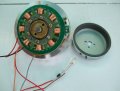
Another option is an old VCR Drum motor, they dont need many RPM & the load is next to nothing. If you wire the 2 sets of windings in series there is ample AC voltage, the LED will need a diode in series. It doesnt need to rotate very fast at all.
 

Attachments

Thread Starter

JBElliott

Joined Mar 12, 2011
12
Another option is an old VCR Drum motor, they dont need many RPM & the load is next to nothing. If you wire the 2 sets of windings in series there is ample AC voltage, the LED will need a diode in series. It doesnt need to rotate very fast at all.
I have an old VCR that just died! I'll have to take it apart and try the motor from that.

Did you mean that "the LED with need a resistor in series"? Or a diode to deal with the hamster going the "wrong" direction.
 

Thread Starter

JBElliott

Joined Mar 12, 2011
12
Thanks again for all the great replies. This has been fun, but seeing as it's a second grade science project, we're going to keep things as simple as possible. Of course I say that planning on tearing open an old VCR to get the motor . . . :D
 

debe

Joined Sep 21, 2010
1,419
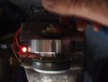
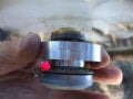
Hi JBElliot, The Reel drive motor gives 2V DC across the LEDS @ 600RPM, & has 2LEDs in oposite polarity so that if the motor is driven one way one LED lights & if driven in reverse the other lights. As that motor generates DC. The Drum motor generates AC so you need a diode in series with the LED. The Voltage across the LED is 1.5V DC.
 

Thread Starter

JBElliott

Joined Mar 12, 2011
12
Hi JBElliot, The Reel drive motor gives 2V DC across the LEDS @ 600RPM, & has 2LEDs in oposite polarity so that if the motor is driven one way one LED lights & if driven in reverse the other lights. As that motor generates DC. The Drum motor generates AC so you need a diode in series with the LED. The Voltage across the LED is 1.5V DC.
Thanks! I understand the need for the diode now. I'll see what I find in the broken VCR we have this weekend.

P.S. Our hamster is too noisy to be a night light, we have to close all the doors just to get some sleep while he's running on his wheel all night!
 

debe

Joined Sep 21, 2010
1,419
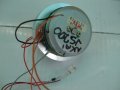
Thaught id put a small fan on each motor & test in a 20Km/h breeze & see which was the easiest to drive with the same size fan. The VHS VCR Drum motor won easily
 

Attachments

Top